Coating thickness measurement method---chronological liquid flow method
The chrono-flow method has the advantages of simple equipment and convenient operation, and the accuracy is ±10% for coatings with a thickness of more than 2 µm. It is a commonly used thickness measurement method.
1) Method principle
The counting liquid flow method belongs to the chemical method. Its working principle is that the test solution with a certain composition flows to the surface of the local coating to be tested in a thin stream at a certain flow rate. Under certain circumstances, until the tested coating is completely dissolved and the bottom metal color appears as the end point, the thickness of the coating is calculated according to the time it takes for the tested part of the coating to dissolve completely. (Related Instruments: Thickness Gauge)
This method is generally applicable to protective coatings and protective-decorative coatings on metal substrates. For example: copper, nickel, chromium, zinc, cadmium, tin, silver, and copper-tin, zinc-copper alloy coatings on steel substrates. It can also be used to measure the thickness of each coating on multi-layer coatings (such as copper_nickel, copper_nickel_chromium, copper-tin alloy_chromium, etc.), and at the same time, the area of the coating to be tested should not be less than 0.3cm 2 .
2) The device of the instrument
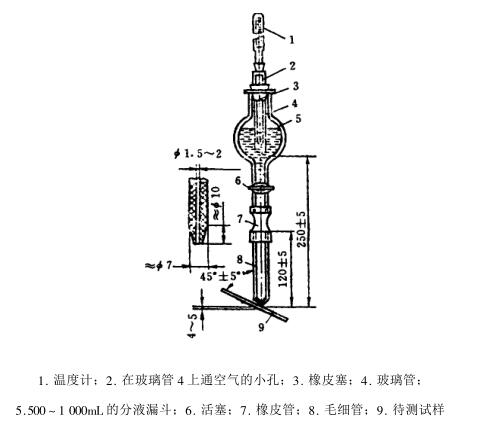
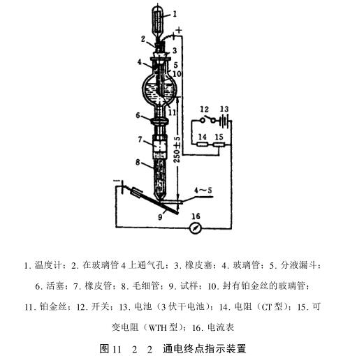
Figure 11_2_1 is the instrument device for thickness measurement by chrono-flow method.
The device is mainly composed of a separating funnel with a piston. The lower end of the funnel is connected to a glass capillary with a rubber tube. The length of the capillary is 12±5mm, the inner diameter is 1.5~2mm, the length of the cone is 10mm, and the outer diameter of the lower end is 1.5~2mm. The caliber of the capillary directly affects the liquid flow rate. Therefore, it is stipulated that when the piston is fully opened and the pressure is stable, at a temperature of 18~2o℃, 1o±o.1mL distilled water should flow out from the separating funnel within 3os.
The glass tube is used to keep the hydraulic pressure stable. The glass tube is inserted into the separatory funnel through a rubber stopper with holes. The upper end of the glass tube is connected with a rubber stopper with holes to allow air to enter the separatory funnel. 25o±m fixed distance, and insert a thermometer in the glass tube. As the solution in the separatory funnel flows out through the capillary, air enters the funnel through the rubber stopper with holes, so that the pressure during the measurement is constant.
In the case of direct observation of the end point, the characteristics of the complete dissolution of the coating are not easy to see clearly for some coatings. In order to indicate the end point objectively, a power-on end point indicator device is added to the chronoliquid flow method instrument (see Figure 11_2_ 2).
In the chrono-flow method thickness measuring device, a platinum wire is sealed at one end of the glass tube on the chrono-flow method, and then the glass tube is inserted into the funnel through the rubber stopper, and its end is level with the glass tube. Then connect the platinum wire and the sample to be tested to the amplifier circuit (12, 13, 14, 15 in the figure).
In this way, when the thickness is measured, the circuit is connected and the piston is opened, so that a current flows between the platinum wire and the tested sample. deflection, using this phenomenon as an indicator to determine the end point.
3) Test solution composition
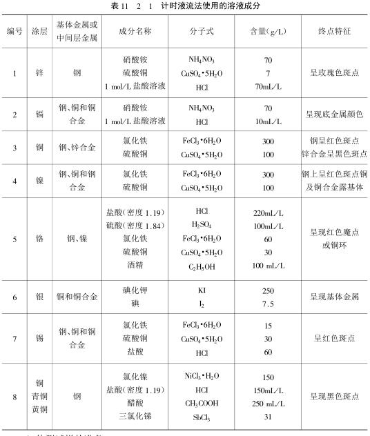
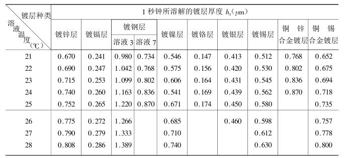
Considering factors such as the dissolution effect and end point display of different coatings to be tested, and requiring constant dissolution per second at different temperatures, various test solutions for different coatings and their corresponding substrates or intermediate coatings are strictly regulated. , as shown in Table 11_2_1. The composition specifications of the prepared test solutions used should be chemically pure (grade 3) or above. The solvent is distilled water.
4) Preparation of samples to be tested
(1) Before inspection, oil and dirt should be removed from the tested part of the coating with gasoline, propane or magnesium oxide paste. After degreasing with magnesium oxide paste, the coating surface should be carefully washed with distilled water and cleaned with filter paper. Blot dry or put it in clean air to dry, such as thickness measurement after coating, it is not necessary to degrease.
(2) For samples whose outermost layer is a nickel-plated layer, in order to remove the passivation film on the surface, after degreasing, use cotton dipped in a 1:1 hydrochloric acid solution to remove the surface film layer, then wash and dry.
3) For samples whose outermost layer is chromium plating, in order to destroy the passivation film on the surface, a zinc rod dipped in the test solution should be used to contact the surface of the coating to be tested. When inspecting the thickness of the lower coating, the chromium coating should be removed in advance with concentrated hydrochloric acid containing 1% to 2% antimony trioxide.
(4) The thickness of the galvanized layer and the cadmium-plated layer should generally be measured before passivation. If the sample has been passivated, the passivation film on the surface should be removed with cotton dipped in hydrochloric acid at a concentration of 1:8. Then wash and dry.
(5) In order to prevent the solution from dispersing, use a special pencil or other chemically stable materials to draw two parallel lines according to the flow direction of the solution on the surface of the tested coating, and the distance between the lines should be about 4mm.
(6) The pretreated sample should be placed in the inspection room until the temperature of the sample is equal to the room temperature before measuring the thickness.
5) Test methods and steps
(1) Preparation of test equipment. After cleaning and installing the instrument as required, add the corresponding test solution into the separatory funnel to 3/4 volume, open the piston to fill the capillary with the test solution, plug the funnel neck with a rubber stopper, and reopen the piston to let the test solution Flow out from the funnel until the air bubbles are evenly sucked into the funnel through the glass tube, which indicates that the pressure in the funnel has stabilized.
If there are air bubbles in the rubber tube or capillary when the solution fills the capillary, it is necessary to open the piston and press the rubber tube tightly to remove the air bubbles. Check whether the flow rate of the test solution meets the requirements.
(2) Installation of the sample. Fix the sample to be tested on the sample holder of the instrument, the surface of the sample should be 4~5mm away from the tip of the capillary, and the angle between the surface of the sample and the horizontal plane is 45°±5°. When it is necessary to energize for end point indication, connect the circuit.
In order to prevent the test solution from dispersing or splashing, add a glass rod on the sample close to the test site, so that the solution flows into an appropriate container along the glass rod.
(3) When the test is officially started, when the piston is turned on and the stopwatch is turned on at the same time. After the test solution dissolves the coating for a period of time, pay attention to observe the color change of the tested surface of the sample (or the swing of the pointer of the ammeter), and immediately close the piston and stop the timing when the end point characteristic appears, and record the action time.
(4) In the case that it is difficult to determine the end point of the copper-plated layer or cadmium-plated layer on the steel substrate, the following auxiliary measures can be used to help correctly judge the end point.
① When the copper layer on the steel substrate is close to the end point, periodically add (1-1) hydrochloric acid solution containing 15% ferric chloride to the inspected part. The end point is characterized by the appearance of dark spots after 2 to 3 seconds after adding the solution
② When the cadmium layer on the iron and steel substrate is close to the end point, add (1-1) hydrochloric acid solution containing 1oog/L chloride table to the supernatant of the inspected part. The surrounding cadmium layer is black.
(5) When it is difficult to observe the dissolution end point of some coatings, it is determined by the electrification timing liquid flow method. When measuring, when the circuit is connected, open the piston and start the stopwatch until the coating is completely dissolved. When the substrate or intermediate coating metal appears, the moment the ammeter pointer deflects, stop the stopwatch and record the elapsed time.
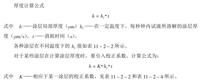
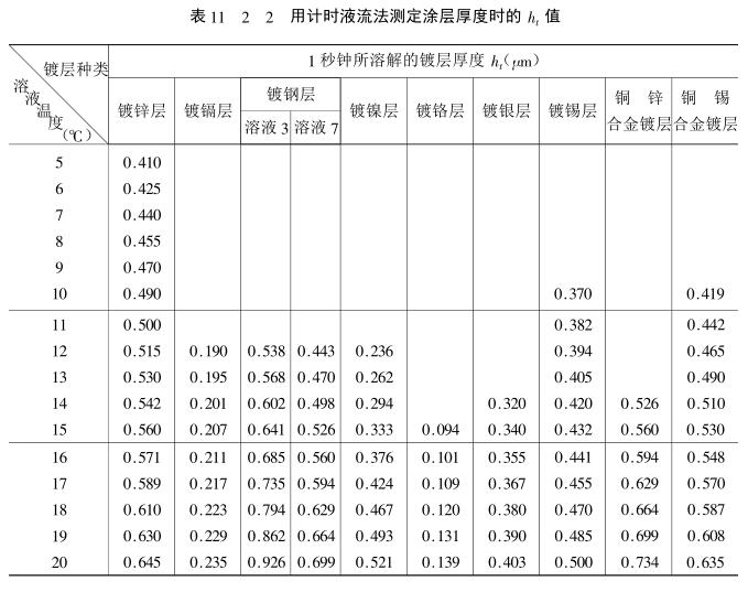
6) Calculation of local coating thickness
- 1What is a Thickness Gauge?
- 2Film thickness determination by magnetic method
- 3Coating thickness measurement technology---magnetic method
- 4Coating thickness measurement technology --- Profile Gauge method and light cut method
- 5Coating thickness measurement technology---drip method
- 6Why should the walls and floor finishes of the living room use moderately sub-toned re-colors?
- 7A Humble Opinion on the use points and precautions of Coating Thickness Gauge, how much do you know?
陈盛江 - 《刍议涂层测厚仪使用要点及注意事项》
- 8Analysis of common measurement techniques for color coated steel film thickness
- 9Application of Ultrasonic Thickness Gauge in Periodic inspection of Pressure Vessel
田双 - 《超声波测厚仪在压力容器定期检验中的应用》