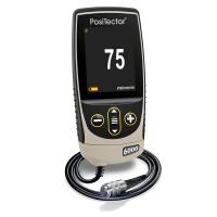
Defelsko Positector 6000 Advanced Coating Thickness Gauge Instructions for use
The Defelsko Positector 6000 Series Coating Thickness Gauge is a handheld, non-destructive coating Thickness Gauge with a larger data storage capacity of up to 100,000 measurements than the standard type, and features such as real-time graphing, graphical prompts, and batch recording.
This article is mainly in detailThe Positector 6000 Advanced Coating Thickness Gauge includes how to turn the gauge on and off, how to use the menu, how to calibrate, verify and adjust, how to use the memory management, how to introduce statistical functions, how to use the menu, and more.
The Defelsko Positector 6000 Advanced Coating Thickness Gauge is available in F and N non-magnetic transducers and FN magnetic/non-magnetic transducers.
The F-probe uses a magnetic method to measure the thickness of a non-magnetic coating on ferrous metals.
The N-probe uses the eddy current method to measure the thickness of a non-conductive coating on a non-ferrous metal.
The FN probe combines all the features of the "F" and "N" probes.
Power on/off method
Press any button to turn it onDefelsko Positector 6000coating Thickness Gauge,To prolong battery life, the coating gauge will automatically shut down if there is no operation within 3 minutes. All settings remain the same.
Measurement operation method
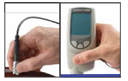
1. Please remove the black main household oak moon sleeve (if any) from the probe for the split probe one, and take out the rubber protective sleeve for the built-in probe onePositector 6000 Coating Thickness Gauge。
2. Press any button to turn onPositector 6000 Coating Thickness Gauge。
3. Hold the probe close to the surface to be measured and maintain this position. When a valid measurement is completed,Positector 6000 Coating Thickness GaugeTwo peaks will sound, and the two-color indicator will flash green and display the measurement data.
4. Move the probe at least 2 inches (5 cm) away from the surface being measured, or take continuous measurements at the same location on the surface to be measured every 2 seconds, without dragging the probe along the surface to one side.
criterion
Measure the uncoated part first! This quick zero-check operation determines if alignment adjustments are needed for the matrix. The accompanying calibration traces are then placed on an uncoated substrate and measured separately to ensure that the attached calibration traces are placedDefelsko Positector 6000 Advanced Coating Thickness GaugeThe measured known thickness is within tolerance.
Menu actions
Control the coating Thickness Gauge function via the menu, access the menu, please openPositector 6000 Coating Thickness Gauge, and then press the OK button in the middle of the coating gauge.

To navigate through the menu, press (-)/(+) to scroll down/up, then pressCoating Thickness Gauge "OK button in the middle".Select and press the (-) (+) button at the same time to exit any menu at any time, or you can select Exit from the menu.
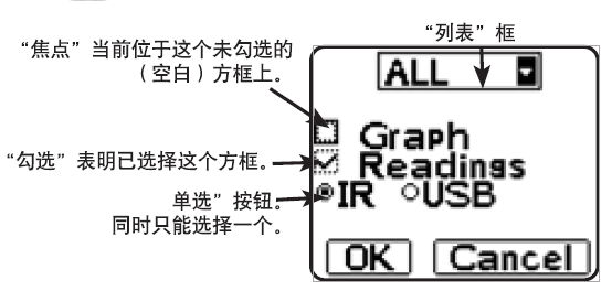
If there are too many menu options to appear on the same screen, a scroll bar will appear. Dark areas indicate the entire menu in your eyesThe section that is being viewed before.
There is a down arrow to the right of the List box, which is used(-) and (+) press i ugly to move up and down until the desired option is displayed, thenPress backCoating Thickness Gauge "OK button in the middle".Select it and move the focus to the next item.
Calibration, verification, and adjustment
1. Calibration is usually done by the manufacturer or a laboratory with appropriate qualifications
2. Accuracy verification is completed by the user
3. Adjust one to a known thickness
calibration
Calibration is a controlled, evidence-proof process that measures and tracks calibration standards and verifies that results are within the nominal accuracy of a coating Thickness Gauge. Calibration is usually performed by:Coating Thickness GaugeThis is done in a controlled environment by the manufacturer or a properly qualified calibration laboratory according to a certified process.
verify
verifyis an accuracy check performed by the user according to a known reference standard, and to successfully complete the verification,Coating Thickness GaugeThe data read needs to be within the accuracy of the combined Thickness Gauge and the reference standard.
adjust
Adjustment or calibration adjustment is to makeCoating Thickness GaugeThe operation of the thickness reading data to be consistent with the data of the known thickness sample, which is designed to improveDefelsko Positector 6000 Advanced Coating Thickness GaugeEffectiveness in a specific surface or an area of the measurement range, which can be adjusted with a single or 2-point calibration, will be stored in the calibration settings.
Note: After each calibration adjustment of the gauge, The symbol disappears.
The Defelsko Positector 6000 Advanced Coating Thickness Gauge is calibrated at the factory and performs an automatic self-test each time it is measured, and in most cases no additional adjustments are required after the reset (11th person), just check if the uncoated substrate is zero (ZER0) and then measure.
However, the Positector 6000 Advanced Coating Thickness Gauge can be affected by different areas of matrix shape, composition, and surface roughness, or the measurement section, so calibration adjustments are provided.
If the reading data is outside the desired range of the thickness of the analyte, a single or 2-point calibration adjustment can be made.
If you do not specify a calibration adjustment method, use the singular method first. If it is not possible to accurately measure the supplied calibration trace, the factory calibration settings can be restored at any time using the 2-point method by resetting and creating a new calibration setting or deleting adjustments made to the calibration 1 calibration setting. The screen will be displayed each time you use the factory calibration settings Symbol.
Note: For "FN" coating Thickness Gauges, calibration adjustments can only be made in "F" or "N" mode (stored in a specific calibration, respectively) and the calibration adjustment obtained from the last time is used.
Note:When you are done adjusting, you can "lock" the current calibration adjustment to prevent this setting from being altered. (See Cal Lock in this article)
1. Single-point calibration adjustment
Also known as a solution or checkpoint, this adjustment can be made using 4 methods:
1)Simple zero-alignment adjustment
Measure the uncoated part. IfPositector 6000 Advanced Coating Thickness GaugeIf "0" is not displayed within the tolerance of the probe used, move the probe away from the surface and adjust the display down (-) or up (+) until the screen shows "0". Measure and adjust until the average of the thickness of the uncoated surface is read multiple times to "0".
(2) Average zero calibration adjustment
Measure the uncoated part. If the coating Thickness Gauge does not display "0" within the tolerance of the transducer being used, move the transducer away from the surface and adjust the display down (-) or up (+) until the screen shows "0". Measure and adjust until the average of the uncoated surface thickness is read multiple times to "0".
1. Select the Zero menu option.
2. Press (+) to select the number of reads to use to calculate the average (usually 3-10 reads).The greater the difference in the read data, the number of reads should be increased to calculate the average.
3. Repeat the measurement of the thickness of the uncoated part, the Thickness Gauge will read next to each otherWait 2 seconds between fetch operations to enable the user to properly position the probe on the surface being measured. After the last measurement, the coating Thickness Gauge calculates the reading data and displays a "0", which represents the average of all zero read operations.
(3) Simple tuning to a known thickness
Sometimes it is necessary to adjust the coating Thickness Gauge to a known thickness (e.g., calibrated trace thickness) instead of zero.
Measure the object to be measured. If the desired reading data is not obtained (within tolerance), move the probe away from the surface being measured, and then adjust the displayed reading data to the desired thickness down (-) or up (+), holding down the button to increase the adjustment speed.
(4) Adjust the average to a known thickness
For rough surfaces or surfaces, the first consideration is to read the known thickness multiple times and calculate the average of the results.hundred
1. Select Single Point Adjustment from the Cal Settings menu(1 PtAdjust) 。
2. Press (+) to select the number of reads to use to calculate the average (usual reads3-10 times). The greater the difference in the read data, the number of reads should be increased to calculate the average.
3. Repeated measurement of known thickness references. The gauge waits 2 seconds between adjacent read operations, enabling the user to place the transducer correctly on the surface being measured, after the last measurement, the gauge calculates and displays the read data, which represents the average of all measurement operations, if the desired read data is not obtained (within tolerance), moves the probe away from the surface being measured, and then adjusts the displayed read data down (-) or up (+) to the desired thickness and presses the "OK button in the middle" of the coating Thickness Gauge.
2. 2-point calibration adjustment
1. Select 2PtAdjust from the Cal Settings menu.
2. Press (+) to select the number of reads to use to calculate the average of the thin item (usually 3-10 reads). The greater the difference in the read data, the number of reads should be increased to calculate the average.
3. Repeat the measurement of thin items. The gauge waits 2 seconds between adjacent read operations, allowing the user to correctly place the transducer on the surface being measured. After the last measurement, the gauge calculates the reading data and displays a thickness value that represents the average of all reads performed using the factory calibration settings.
4. Move the probe away from the surface being measured, and then down (-) or up (+) adjust the displayed read data to the known thickness value of the thin item. Press the Middle OK key to accept the value.
5. Repeat steps 2-4 for thick items.
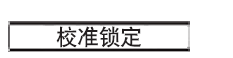
When selected, a Lock icon is displayed and the current calibration settings are locked to prevent the user from making additional adjustments.
User mode calibration
In some cases, single-point and two-point calibration is not effective, such as when measuring conductive coatings on magnetic coatings or non-metals. In these cases, the included Posi Soft software can download special calibration settings.
3. Calibrate the memory
It is useful to save a specific calibration adjustment before making a new one.
If you return to this section later, you can resume the corresponding calibration settings.
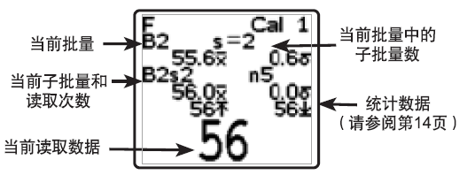
Any 1- or 2-point calibration adjustment can be "set", and the PosiTector 6000 Coating Thickness Gauge always displays the current calibration setting (e.g., Calibration 3) in the upper right corner of the screen.
The setting, called Calibration 1, has a special feature. You can adjust the setting, but you can't delete it, and it will always be activated after resetting the factory settings.

New calibration settings (up to 10) are created with the next available number, and by default, these new calibration settings are created using the factory settings of the gauge. It starts with icon representation (displayed at the bottom of the drop). If bulk is turned on and contains read data, a warning message is displayed that prevents you from creating a new Cal Memory. Delete the batch first.
Load the existing settings. Use the (-) (+) button to scroll up and down in the List box until the desired settings are displayed, then press the "Intermediate OK Key". If the master batch is turned on and contains read data, a warning message is displayed that prevents you from opening the stored calibration settings. Start by creating a new batch or opening a batch that does not contain read data.

Effectively removes a setting from the list. After that, you can use New(New) command to reuse the calibration number. If you have already used the calibration setting to store read data in batches, you cannot delete the setting. Please first delete all read data in the batch (see Memory Management), although Cal 1 cannot be deleted, but the Delete function will restore it to factory settings.
Use the coating gauge's built-in lR port to send a complete list of calibration settings to the lR printer, or to your PC's default printer using the included USB cable.
Memory management
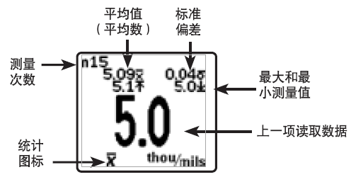
Defelsko Positector 6000 Advanced Coating Thickness GaugeUp to 10,000 measurements can be recorded, up to 1,000 groups (batches) can be set, and are suitable for display on the screen for statistics, printing on the optional lR printer or PC's default printer, or downloading to a personal computer via the included PosiSoft software and USB cable. Recordings of reads are also time-stamped.
Close any batch that is currently open and create a new batch name with the next high digit number. For example, if there is only batch 1(Batch 1) and Batch 3 (Batch 3), create Batch 4 (Batch4) and treat it as the current batch. will be displayed Icons and basic statistics. Thereafter, each measurement will be displayed on the screen while it will be stored in this new batch. Screen statistics will be updated in real-time with the results of each measurement, and new batch names will be time-stamped when they are created.
Note: When opening a batch, you can press (+) to create a new batch
 (Displayed only when bulk is opened)
1. Create a new sub-batch. In this example, B2s2 is a subbatch of Batch2. Subbatches enable users to group related batches, and the corresponding statistics are grouped into individual subbatches, with Batch 2 containing statistics for B2s1 and B2s2.
Shortcut: When opening a subbatch, you can press (+) to create a new sub-batchbatch

The PA2 function helps the user determine if the film thickness over a larger area meets the user-specified minimum/high level.

Select the batch or subbatch name you created earlier to open it or make it the current batch/subbatch. If it contains measurement data, the on-screen statistics will immediately reflect the values calculated from that batch, and the calibration setting associated with that batch, Calibration 2, will be opened.
Stop recording, close the current batch or subbatch and clear the stats on the screen.

Effectively deleting a batch or subbatch from memory deletes the corresponding name and all measurement data. You can divide the sub-batches one by one]. To delete all related sub-batches, simply delete the top batch.
All read data of the current or recently used batch or sub-batch is listed on the screen, the last 10 measurements are displayed at the base, the content can be scrolled by pressing the (-) or (+) button, and the page by page can be scrolled by pressing and holding the group for 1 second.
To change or remove a value, scroll to the value (align the "+" sign on one side with it) and take one more measurement to change it, or you can press the delete it, or press the "OK key in the middle" to exit the feature, and the statistics will be updated.
Quick Method:To exit, press the (-) (+) button at the same time.

Use the built-in lR port to output statistical summaries to an optional lR printer, or use the included uSB cable to output statistical summaries to your PC's default printer. If the Readings box is checked, the measurements and their timestamps will be printed at the same time, and if the Graph box is checked, a histogram will be printed. If HiLo Alarm is enabled, the upper and lower limit calculation results are printed using the current HiLo setting.
Note: This calibration cannot be adjusted if the measurement is made with the corresponding settings and the results are stored in the batch.
Press (-) to delete the previous read from the currently open batch.
1. Download the measurement data stored in memory
You can use the included USB cable and PosiSoft software to will(batch) under the measurement data stored in the gauge memorycarryto the computer. Once the download is complete, the measurement data in memory is not deleted.
The CD contains PosiSoft version 2. 1 1 or later, you can use it to download read data to your computer, you can run it on a Windows-based computer equipped with a USB port with Microsoft Windows®2000 SP3 or later, it enables you to enter notes and instructions, print histograms and basic charts and implement data management, and you can also export read data to a document or spreadsheet.
Statistical functions

When you select Statistics, it will be displayed on the screen Icons and statistical summaries.
Press the (-) button to delete the previous measurement data, and press (+) to clear the statistics.

This mode allows the gauge to graphically and audibly warn the user when the measurement data is outside of the user's specified range.
When you select the HiLo Alarm for the first time, the current Lo setting is displayed. Adjust down (-) or up (+), you can also measure coatings with a thickness close to the desired value, and use the button to make the final adjustment, select the group continuation (NEXT) to accept the value, and the current setting will be displayed. Follow the same steps to adjust the setting and it will be displayed on the screen Icon.
Icon.
At this point, the measurement data is compared to the range you specify, and if the measurement is within this range, the gauge will beep twice and flash green, if the measurement is below the lower (Lo) limit, it will emit a bass, and if the measurement is above the upper limit (Hi), it will emit a high sound. If the read data is outside this range, the indicator will flash red and press (+) to clear the upper and lower limits (HiLo) read data.

One will be all the statistics and upper and lower limits in the screen(HiLo) list is zeroed.
Settings menu

Reset returns to factory settings and resets the gauge to the state it was known when it was unboxed, after changing the settings(If the gauge is not working properly or cannot be calibrated.)quasi-adjustment), which is very useful.
The following actions will be performed:
1. Close all batches and delete the stored measurements.
One Clear all calibration settings and revert to the gage's factory calibration settings(Calibration 1).
This symbol will be displayed on a screen:  If the user makes a calibration tunewhole, it will disappear.
OneMenu settings revert to the following:
High Score = Off (Hi Res = OFF)
Memory=OFF (Memory=0FF)
Cal Lock= OFF
Statistics=0FF
Hi LoAlarm = OFF
N Lock= OFF (FN type only)
You can also perform a more efficient Reset by holding down the (+) button to turn off the gauge until the reset symbol is displayed 。 This is useful when the gauge cannot be turned on or used normally, as it does the same thing as a menu reset, in addition to setting the following: Units = μm, Flip Display = Normal, and Language = English.
Note:
1. During the reset process, make sure the gauge is away from the metal.
1. Reset does not affect the date and time,
This option allows the screen content to be displayed in reverse, which is suitable for workbench operations(split probe) and overhead operation (built-in probe) allows the operator to easily read the results display.

When Hi Res is selected, The resolution of the displayed gauge changesIt is as follows:
resolution
0.01 mil 0.00-99.00 mils
0.1 mil 100.0-999.9 mils
0.1 um 0.0_999.9um
0.01 mm 1.00-99.99mm
Note: Hi Res mode does not affect gauge accuracy.

The menu button converts the on-screen display content and all stored read data from imperial to metric and vice versa.
All batches are time-stamped when they are created, and all measurement data is time-stamped when stored in those batches (in a 24-hour format), so you need to use the menu button to ensure that the date and time are correct, you can also connect the gauge to PosiSoft and use the Gage Utilities-> Set Clock feature >in PosiSoft to automatically update the date and time.
Split probes
The split probe Thickness Gauge is powered by the Thickness Gauge hostand rational composition. A variety of specifications are availableInterchangeable probes, each probe can be kept fromUnique calibration information. All Thickness GaugesAny probe can be used with the main unit. To unload the probehead, please turn off the gauge and position it horizontally
Pull the plastic probe connector (in the direction of the arrow) to remove it from the gauge unit.
When the PosiTector 6000 Coating Thickness Gauge is turned on, it moves white to determine the type of probe to be attached and performs a self-test, it "senses" and makes a measurement attempt every 2 seconds when the probe is close to metal, and when it is far away from metal, the gauge stops sensing ifAfter 3 minutes without any operation, the gauge will automatically turn offMachine.
The continuous measurement function is only suitable for careful measurement when the probe is placed on a small surface or an irregularly shaped surface. pleaseIgnore all reads before the probe etchs the surface being measuredOccupy. Never drag the probe to one side.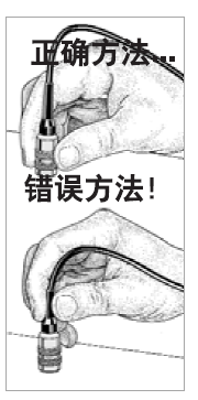
1. Standard probe
These constant-pressure, stainless steel probes are completely sealed and waterproof – making them ideal for underwater operations. Pinch the 2 knurled rings on the probe and press down on the spring-loaded sleeve on the outside.
2. FN combination probe
The FN probe combines the functions of an "F" and "N" probe. The two types of probes will be switched automatically. The probe first attempts to measure using a magnetic method. If the layer is a non-magnetic material on steel, the letter F is displayed. Gouzer, the probe automatically tries to measure using the eddy current method. If the coating is a non-conductive material on metal, the letter N will be displayed.
Non-iron-based locking(This option is only available for FN combo models)
For routine measurements on non-ferrous matrices, select N Lock. When the probe is measured, only the eddy current method is used, which can shorten the measurement time and extend the battery life.
N Lock is also suitable for measuring substances such as coatings on the outside of thick steel plates.
Optional accessories
We offer a variety of accessories to help you get the most out of your PosiTector 6000 Coating Thickness Gauge.
temperature
Operating Range: +32 to +120°F (0 to +50°C)
The Posifector 6000 Coating Thickness Gauge automatically compensates for temperature. Wait a few moments for the probe to reach ambient temperature before starting the measurement.
Ignore the first data measured when the temperature is different. When measuring surfaces where the temperature is significantly localized or lower than the ambient temperature, keep the probe at least 6 inches (15 cm) away from the surface being measured and ensure that the probe is 1 second above the surface between measurements.
Tip: You can use the PosiPen8 for extreme temperatures at a 150 toMeasured on ferrous matrices between +450°F (-100 and +230°C). It is suitable for measuring small, hot, or hard-to-touch raw surfaces.
Replace the battery
When a new alkaline battery is inserted, the battery icon It is displayed as four bars, and the number of J bars decreases as the battery level gradually decreases, when the battery icon drops to 1 bar
 , you can still use the Defelsko Positector 6000 Advanced Coating Thickness Gauge, but you should replace the battery as soon as possible, using only "AAA" alkaline batteries You can also use wire t-height and wire hydrogen rechargeable batteries, but the gauge will show a low battery.
In order to retain all user settings and read data stored in memory, replace the battery only when the Defelsko Positector 6000 Advanced Coating Thickness Gauge is turned off.
Troubleshooting
Our website provides some of the most common problems reported by the customer service department and their possible causes, most of which can be resolved using Reset.
The product is sent for repair
Before Sending the Thickness Gauge Back for Repair_
1. Insert a new alkaline battery into the battery according to the correct polar directionin the cabin.
2. Check whether the tip of the probe is sticky or damaged. The probe should be able to be attachedIntention up and down activities.
3. Perform a Thickness Gauge Reset (Page 15)
4. Place the calibration foil in the metal (according to the Thickness Gauge for "F" alsois "N", ferrous or non-non-ferrous) on an uncoated substrate and measured.
Send it back if neededDefelsko Positector 6000 Advanced Coating Thickness GaugeFor repair, please provide a detailed description of the fault and the measurement results (if any) Contact the customer service of Nanbeichao Mall.
Technical data
Gauge host size:5.75 x 2.5 x 1.2 inches (146 x 64 x 31 mm)
Battery life: 5o hours of continuous use/36,000 data reads.
The above isFor detailed instructions on how to use the Defelsko Positector 6000 Advanced Coating Thickness Gauge, and to learn more about Defelsko Thickness Gauge products, please enter:/b/Defelsko
- 1Measure gloss with a PosiTector GLS gloss meter
Defelsko
- 2Measuring the thickness of sprayed truck backing
- 3PosiTector 200 ® Operation Manual V 3.1
- 4PosiTector UTG Ultrasonic Film thickness probe - Operating principle
- 5PosiTector Software Update Instructions
- 6Which probes is the PosiTector host suitable for? A table tells you
- 7PosiTector 6000 Coating Thickness Gauge FAQ
- 8Defelsko Instruments integrates with third-party devices and applications
- 9PosiTector SPG Roughness Profile Gauge FAQ
Defelsko - 《Defelsko》
-
![Defelsko PosiTector 6000 FNS1 coated platings Thickness Gauge that automatically converts in magnetic and nonmagnetic environments]()
-
![Defelsko PosiTector 6000 FS1 Coating Thickness Gauge Iron metal substrate (such as steel) nonmagnetic coating]()
-
![Defelsko PosiTector BDYSTD Standard host, new, probe available separately]()
-
![Defelsko PosiTector 6000 FNS3 Coating Thickness Gauge metal substrate Automatic substrate type identification and measurement]()
-
![Defelsko PosiTector 6000 FS3 Coating Thickness Gauge Iron metal substrate (steel, iron, etc.) Split probe type]()
-
![Defelsko FTRS Thickness Gauge Probe]() Defelsko FTRS Thickness Gauge Probe$ 904.00
Defelsko FTRS Thickness Gauge Probe$ 904.00