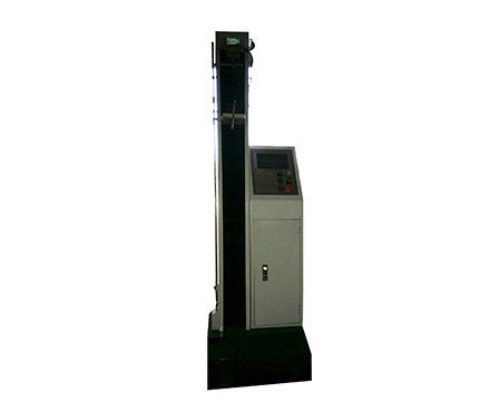
Determination of film strength on Force Gauge
The components of the instrument for measuring the tensile strength of the paint film (Figure 138) include a base frame 1 on which a lever 2, clamps 3 and 4, a driver and arc dials 5 and 6 are installed. Clips 3 and 4 are used for fixing the paint film. The lower clip is connected with the shaft 7, and the flywheel 8 with the handle rotates to drive the shaft 7 through the tapered transmission. The upper clip 3 is then connected together with the counterweight on the red rod 2 by the metal strip.
When rotating flywheel 8, clip 4 just descends, so paint film is elongated; Gripper 3 also descends simultaneously. After this, the red rod 2 with the counterweight is tilted, so that the stress used by the paint film to pull the watch is indicated on the arc dial 5 . The following clip 4 is connected with the pointer 10 by the pull rod 9, and the pointer 10 shows the elongation of the paint film on the dial 6; elongation. Because when stretched, both clips land down. Therefore, the dial 6 is fixed on the pole 2, and with the help of the pole, it can move simultaneously with the upper clamp.
The clip 4 can be fixed on the shaft 7 by means of a set screw 11 . During the test, the screw 1 is removed, and the clip 4 is blocked on the upper end of the shaft 7 by the paint film itself. At the moment when the paint film breaks, the clamp slides down along the shaft 7, thereby disengaging the pull rod connecting the shaft 7 and the pointer 10, and the pointer shows the secondary length of the paint film at this moment. (Related instrument: Tensile testing machine)
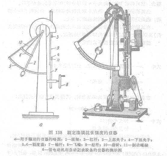
There is a toothed groove on the dial 5, and the stop catch on the lever 2 can move in the opposite direction along the sliding well and stop the lever. Thanks to this device, the lever and the pointer retain the position they occupied when the paint film was broken, so that it is possible to read their numbers after the paint film breaks. During the test, put the paint film between two millimeter coordinate papers, and cut a rectangular sample from the middle of the paint film with the help of a special die or safety blade, with a length of 60 mm and a width of 5.10 mm. Or 15 mm,. (This depends on the technical conditions). After that, measure the thickness of the paint film left in the adjacent area of the cut paint film with a micrometer (related instrument: Thickness Gauge), and measure six places in total. The tolerance between individual determinations shall not exceed 5 µ.
Rotate the flywheel 8 to make the clip 3 rise as much as possible, fix the paint film between the two paper strips in the clip, cut the paper strip and the paint film together, so that each end is clamped by the clip 5 mm, and the remaining 50 mm is exposed outside. after the specimen is clamped. Use scissors to cut off the unclamped part of the strip. Then rotate flywheel 8 to make clip 4 descend with the speed of 100 millimeters per minute.
When the paint film is slightly taut, take off the stop screw 11 with your left hand, but do not stop turning at the same time. Continue to rotate at a constant speed until the paint film breaks.
At the end of the test, record the readings on the curved dial 5 (breaking load in grams) and dial 6 (secondary length in millimeters).
Example: Test a paint film sample with a width of 6 mm. When measuring its thickness, the following readings were obtained on the micrometer; 55;50;.55;50;55;55u. After the paint film breaks, the price rod 2 (manual or driven by electric motor) stops on the scale corresponding to 350 grams of load on the dial "5", and the pointer S on the dial "6" stops at the equivalent On the scale extending f8 mm.


- 1ASTM paint film physical properties related testing standards
- 2A list of imported testing instruments for paint film testing
- 3Effect of Epoxy Emulsion Types on Properties of Paint Film
陈深填 - 《华南理工大学 化学与化工学院 》
- 4Solid dry film performance inspection
- 5Influence of surface condition of hot-dip galvanized steel sheet on film performance
潘燕芳;杨芃 - 《材料保护》
- 6Analysis of factors affecting film performance of electrostatic painting line
高月莲 - 《表面技术》
- 7Effect of Ultraviolet curing paint Spreader on Wooden ground floor film performance
孙伟圣;王艳伟;徐 立;杨植辉;张秋娟;晁 久;吴忠其;李先春 - 《木材工业》
- 8Effect of surface tension on emulsion paint and film performance
高海伟 - 《涂料工业》
- 9Principle of film formation and influencing factors of film performance
郑顺兴 - 《涂料与涂装科学技术基础》