Tensile machine fault analysis and repair
In high-temperature gold alloys and medium-high-low-carbon alloy materials, mechanical and mechanical properties need to be tested, and the detection of tensile state properties of materials is a very critical and important testing item for axial static tensile experiments of dimetallic materials. This paper mainly introduces several common fault problems and maintenance methods in the production and application of JL-3000 mechanical multi-functional testing machine, WJ-10B mechanical multi-functional testing machine and WDW-300 microcomputer-controlled electronic multifunctional testing machine.
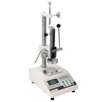
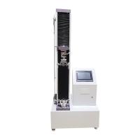
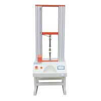
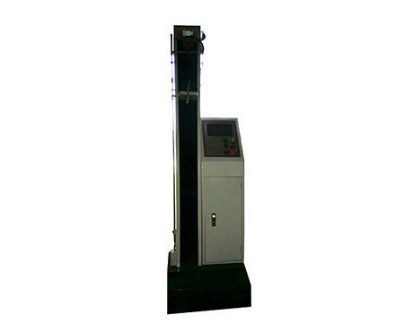
At present, the equipment used for axial static tensile test projects of metal materials in the workshop includes JL-3000 mechanical multi-functional testing machine, WJ-10B mechanical multi-functional testing machine and WDW-300 microcomputer-controlled electronic multifunctional testing machine. Among them, JL-3000 and WJ-10B mechanical multi-functional testing machines can not only do tensile tests at room temperature, but also can do high-temperature tensile tests at 200°C~900°C according to the requirements of materials to determine the mechanical properties of materials at high temperatures.
There were many failures in the use of these experimental machines, which seriously affected the quality of the inspection and the progress of the inspection. In order to discuss the maintenance technology of tensile machine with maintenance workers, a few examples are selected to introduce the analysis and treatment methods of faults.
1 Case analysis and processing
1.1 Fault symptom 1
In the normal inspection of JL-3000 Tensile Testing Machine, when the tensile force increases to 2500N (full scale 3000N), the tensile speed suddenly decreases; And this phenomenon can be repeated.
1. 1. 1 Failure analysis
According to the tensile machine working normally below 2500N, and this process is repeatable, it means that the main circuit and control circuit, the mechanical part is normal. When approaching 2500N, the tensile speed decreases significantly, combined with the analysis of the electrical control principle of the tensile machine, with the elongation of the experimental sample, its tensile force increases, and the current of the driving DC motor also increases, which requires the terminal voltage of the driving DC motor to increase accordingly. If the voltage at the motor end is not increased accordingly, the motor will slow down due to the heavy load until it stops. The control signals that control the voltage at the end of the motor are current positive feedback and speed negative feedback. On the other hand, if the motor current is too high, in order to protect the motor from overcurrent damage, the current cut-off negative feedback signal will force the motor to stop rotating. After analysis, the focus of the inspection is on the current positive feedback and current cut-off negative feedback parts.
1. 1. 2 Inspection and Treatment
First of all, check that the positive current feedback resistance 2WR and the current cut-off negative feedback resistance 3WR are normal. Then set the pulling speed to 4mm/min, and when doing the tensile test, it was found that the terminal voltage of the DC motor increased with the increase of tensile force, indicating that the electrical control part was normal, and when the tensile force reached 2500N, the pulling speed dropped suddenly. After the shutdown, adjust the positive feedback potentiometer 2WR, and experiment again with the fault phenomenon as before, and it can be concluded that the current cut-off negative feedback signal will reduce the speed of the motor. It is explained that the midpoint potential of the original potentiometer 3WR varies due to long-term use of the device. Therefore, the current cut-off negative feedback potentiometer 3WR was adjusted, and the fault phenomenon was eliminated after the experiment was started.
1.2 Fault symptom 2
The tensile speed of the LJ-3000 Tensile Testing Machine is unstable when the sample is examined.
1. 2. 1 Fault checking
At a given pull speed of 1 mm/min, 2 mm/min, and 4 mm/minThe actual values measured with the dial gauge are shown in Table 1.
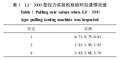
From the above measured data, it can be seen that the pulling speed is generally low, the linearity is not good, and the stability is poor, and the machine can not meet the requirements of sample detection.
During the inspection, it was found that the speed of the rise of the tensile machine was more stable than the rate of decline. A set of measured data at a given pull speed of 1 mm/min, 2 mm/min, and 3 mm/min is shown in Table 2.
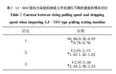
As you can see from the measured data above, the rising rate is nearly 20% lower than the falling rate, and the important thing is that it is stable.
1.2.2 Failure Analysis
Combined with the electrical principle of the Tensile Testing Machine, the control of the tensile machine to rise and fall only changes the direction of power supply to drive the DC motor, and the electrical and mechanical structures are the same. On the other hand, the transmission ratio of this tensile machine is large, which can completely eliminate the influence of the weight of the moving platform on the ascent speed. Obviously, the ascent rate is much lower than the lower one
The deceleration rate is not due to mechanical characteristics, but to the electrical part of the tensile machine when it is lowered. From the analysis of the adjustment control principle of the machine, it is believed that if there is a problem with the tachogenerator part, the above-mentioned inconsistent lifting speed will occur. According to the relatively stable rise speed, the tachogenerator itself is normal, and its output brushes may be in poor contact with the slip ring, causing the output voltage to fluctuate.
1.2.3 Troubleshooting
Based on this analysis, the brushes of the tachogenerator were processed. After system adjustment, the measured values at the given pulling speeds of 2 mm/min, 3 mm/min and 4 mm/min are shown in Table 3.
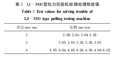
After the fault is handled, the operator believes that the Tensile Testing Machine has a stable tensile speed, which can fully meet the requirements of the tensile test speed and can be put into use.
1 . 3 Fault phenomenon 3
When the WDW-300N microcomputer-controlled electronic multi-function testing machine was used for axial extensometer measurement, the detection display value was seriously low.
1.3.1 Failure Analysis.
Combined with the analysis of the electrical control schematic diagram of the machine, due to the fact that the machine is in
When the sample displacement test is carried out, it works normally, indicating that the electrical control, mechanism drive, signal conversion and display part of the machine are normal. The displacement signal and the axial extensometer signal are detected by two A/D circuits. Obviously, the focus of the inspection should be on the axial extensometer A/D detection circuit.
1.3.2 Inspection Processing
Calibration with a calibrator (0.5mm/revolution). Adjust the calibrator 11 turns, or 5.5 mm. The instrument shows that the displacement value is only 1.25mm, which is higher than the input of 5. 5mm is much smaller.
1 . 3. 3 Test extensometer A/D
Check the extensometer supply voltage on the circuit V= 1. 091V (normal should be 6V); Further check that the voltage regulation transistor on the A/D circuit C1008 is broken. After replacing this transistor, V=5. 91V。
1.3.4 Inspection
Correction is still used with the standard definition (0. 5mm/circle).
Number of revolutions The instrument displays the value/mm
0.603 on one turn
Second lap 1.210
Three laps 1.815
Four turns 2.435
Five laps 3.042
Six laps 3.655
As can be seen from the above data, the correction value is proportional to the test value, and the measurement shows that the value is normal.
1.4 Fault symptom 4
When the WB-10B Tensile Testing Machine is rising and descending quickly, the response lags seriously. That is, when you press the fast up and down button, the fast up and down button does not work, and you can only press and hold the fast up and down button for a longer time.
1.4.1 Failure Analysis
In the WJ-10B tensile machine, the fast lifting and slow lifting are driven by two motors and the same specimen table.
The rapid lifting is to make the lower specimen table move a large distance in a short time when the specimen is replaced, and it is driven by a three-phase AC motor; The slow lifting is driven by a DC motor to carry out a tensile test of the sample. The mechanical changeover between the two drive modes is carried out by a single clutch. When the clutch is energized, it is detached from the fast lifting mechanism, and the DC motor drives the sample stage to rise and fall slowly, and when the clutch loses power and does not work, the fast lifting mechanism is engaged, and the sample stage is driven by the AC motor to rise and fall quickly. Obviously, to check for this fault, for the mechanical aspect, the first thing to do is the clutch conversion mechanism. The second is the contactor that controls the fast lifting motor, etc.
1.4.2 Inspection Processing
When the machine is turned on, the clutch slip ring voltage is measured to be 10V, and the clutch engages (but very slowly); When performing the fast lifting and descent operation, the power supply is zero, and the clutch does not work at this time (disconnect the slow lifting mechanism). According to the analysis of the electrical principle, when the clutch is slowly lifted, it is about 23V, and now it is 10V. Indicates that the clutch power supply DC circuit is faulty. Because the voltage is very low, the clutch suction is not enough, the slow suction, the rebound force is not large after the power loss, and the slow lifting mechanism cannot be quickly disengaged, which is the reason for the lag in the fast rise and fast drop response.
When checking the DC circuit of the clutch power supply, it was found that a rectifier diode (2CZ12B) was broken and damaged, and after replacing this diode, the DC output voltage was 23. 2VDC。 The fault phenomenon is eliminated after the machine is turned on.
1 . 5 Fault phenomenon 5
When the WB-10 Tensile Testing Machine is working slowly, it cannot be stopped by pressing the stop button (the DC motor continues to work), and it takes a long time to press and hold the stop button for the DC motor to stop working; However, when the tensile machine is working slowly, press the stop button to stop.
1.5.1 Failure Analysis
Since the tension machine is working slowly, pressing the stop button can stop the machine, indicating that the stop button is normal (shared). There are two reasons for the above-mentioned fault phenomenon, one is that the contact of the relay YC that controls the slow lifting work is temporarily "sticky", and each contact cannot be disconnected after the coil breaks, and continues to provide power to the DC motor through its contacts, so that the motor continues to work; The second is that the YC relay movable core has strong remanence, after the relay coil loses power, due to the remanence, the movable core is still engaged and cannot fall off immediately, so that the controllable contact can not be disconnected.
1.5.2 Inspection Processing
First of all, the YC relay contacts were inspected and there were no signs of "sticking". It may be that the remanence of the relay core is strong. The fault was eliminated after the relay was replaced.
2 Concluding remarks
Because the electrical control circuit of the Tensile Testing Machine is particularly complex, there are many faults, which are different, and the tensile instability factor is a common fault problem, and there is also a certain degree of difficulty in the difficulty of maintenance, and the inspectors need to attach great importance to it, carefully analyze and summarize various fault problems, so as to solve the maintenance.


- 1Tensile machine application in various industries
- 2Technical analysis of key parameters of Tensile machine: Scientific selection from force measurement accuracy to Power system
- 3Tensile machine purchasing guide [dry version]
- 4Talking about the performance test of epoxy resin film coated on PET
- 5ASTM D5019 Single-layer roofing film reinforced CSM board (chlorosulfonated polyethylene (PE)) standard interpretation
- 6The purpose of tensile testing and its application in the plastics industry
- 7Common problems and solutions in tensile testing
- 8What problems can be caused during tensile testing?
- 9What is tensile strength testing and which products can be tested?
-
![Spring Tensile Testing Machine HT-50P Hyperion tensile machine with printer]()
-
![Patek Jushi LY-7012C Tensile Tester 1000KG]()
-
![BaidaJUSHI LY-7012A Small Tensile Testing Machine 200KG]()
-
![CHINA NBC-1024-2 Tensile Tester 5T]() CHINA NBC-1024-2 Tensile Tester 5T$ 6635.00
CHINA NBC-1024-2 Tensile Tester 5T$ 6635.00 -
![CHINA NBC-6820 Ring type initial tacking machine Tensile Tester]()
-
![CHINA NBC-1023-1 Computerized Double Column Tensile Testing Machine]()