DHT-200 Leeb Hardness Tester operation manual
1. Overview
DHT-200 Leeb Hardness Tester uses the Leeb principle to test the hardness of a variety of metal materials. This instrument is particularly suitable for its small sizeComplete inspections in a variety of work environments. According to the national standard GB/T 17394-1998, the Leeb hardness can be easily converted toCommonly used hardness systems for HRC, HRB, HV, HS.
Before using the instrument, please read the user manual thoroughly to understand the performance of the instrument and master the use of the instrument.
2. The measurement principle of Leeb hardness
2.1 History of the Leeb hardness measurement principle
In 1978, the Leeb hardness measurement method was introduced for the first time in hardness measurement technology, which is defined as the rebound of an impactorThe velocity is divided by the impact velocity of the impactor body and multiplied by 1000. For specific metal materials (e.g. steel, aluminum, etc.), the Leeb hardness value reflects the materialThe hardness relationship of the material, and the Leeb hardness value can be converted into other statically measured hardness values (e.g. HB, HV, HRC, etc.).
2.2 Definition of Leeb hardness measurement
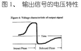
The impact body with tungsten carbide ball head hits the surface of the measured workpiece under the action of the release spring, and produces a rebound. Take advantage of the followingMethod: The downward and bouncing velocity of the impactor is measured at a distance of 1 mm from the surface of the workpiece to be measured: the impactor with a built-in permanent magnet is passing through the lineWhen turning, a voltage is generated in the coil that is proportional to the impact velocity, and the Leeb hardness is calculated by the following formula:
HL=1000×( V b / V a )
Where: HL stands for Leeb hardness
V b represents the voltage generated when the impact body rebounds
V a represents the voltage generated by the impact of the impacting body
Figure 1 shows the voltage generated by the impact and rebound of the impactor:
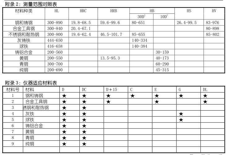
The hardness values measured by the Leeb principle can be directly converted into other hardness systems, such as Vickers (HV), Rockwell (HRC, HRB),Brinell (HB) and Shore (HS).
2.3 Symbol for measuring Leeb hardness
In the same way that traditional static hardness measurements produce different results at different pressures, different impact devices are used to measure the same in the Leeb hardness measurementDifferent Leeb hardness values are also obtained, e.g. 720HLD≠720HLC.
Since the Leeb hardness value is measured by the corresponding impact device, its Leeb hardness value should be included in the conversion to other hardnessesThe impact device used for measuring, e.g. the Leeb hardness value of 510HLD measured with the D-type impact device, should be replaced with a Rockwell HRCWritten:
510,20 HRCLD
Where: 510 is the Leeb hardness value
20 is the converted hardness value
HRC is the value converted to Rockwell hardness
L indicates that the measurement is made by the hardness measurement method on the Richter scale
D indicates the use of a D-type impact device
3. Pretreatment of the tested workpiece
In order to obtain accurate and stable data in the actual measurement, corresponding requirements are put forward for the workpiece to be inspected.
3.1 Requirements for the surface of the workpiece
a) The surface temperature of the measured workpiece should not be overheated< 120°C;
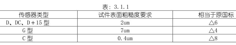
b) The requirements for the surface roughness of the measured workpiece are shown in Table 3.1.1
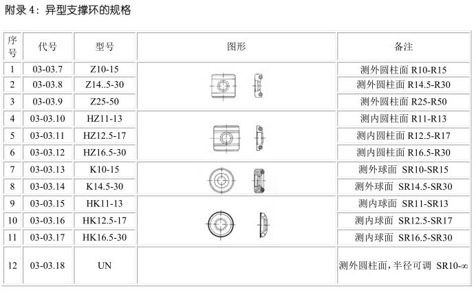
c) For the test of the measured workpiece with a curved surface diameter of less than 30mm, a small support ring or a corresponding heterosexual support ring should be usedThe selection requirements are described in Appendix 4 (pg. 28).
3.2 Requirements of the Hardness Tester for the weight of the measured specimen
a) Specimens weighing more than 5kg, which do not require support;
b) Specimens weighing 2-5kg, specimens with overhangs and thin-walled specimens should be supported by objects during testing to avoid impact force causing testsdeformation, distortion and movement of parts;
c) If the weight is less than 2kg, it should be tightly coupled with the support body weighing more than 5kg, and the surface of the specimen and the coupling body should be flat and smooth.The amount of couplant (alum ± forest, engine oil, etc.) should not be too large, and the test direction should be perpendicular to the coupling plane.The weight and thickness requirements of the measured workpiece are shown in Table 3.2.1

3.3 Requirements for the surface hardening layer of the test piece
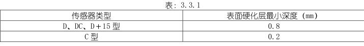
The hardened layer on the surface of the specimen is too thin, and the impact force will penetrate the hardened layer and cause the Incorrect Richter shift value. The depth of the hardened layer should be fullFoot table 3.3.1 Requirements:
3.4 The surface of the test piece must not have strong magnetic properties
3.4 The surface of the test piece must not have strong magnetic properties
Because the strong magnetism has a relatively large impact on the coil of the sensor, which affects the accuracy and stability of the data during measurement, it is used in measurementAvoid strong magnetic materials as much as possible.
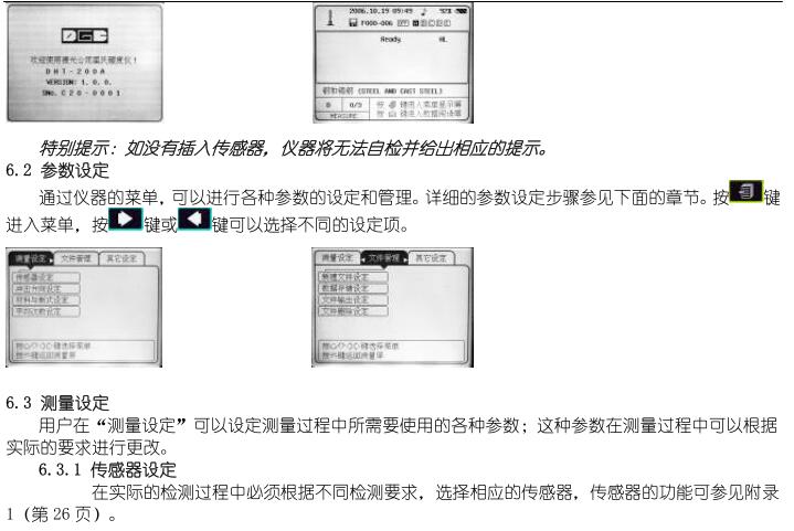
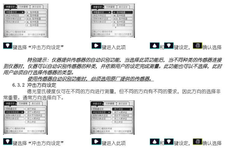
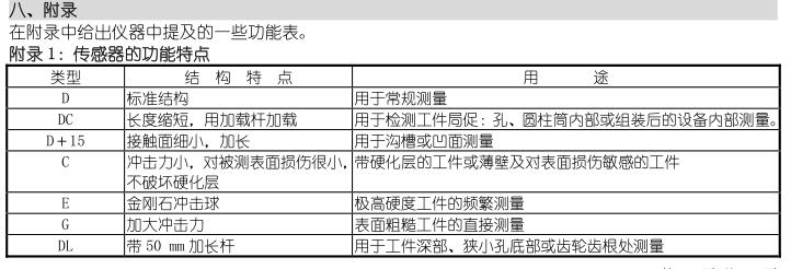
Fourth, the selection and use of sensors
4.1 Selection of Sensors:
In the actual measurement process, due to the requirements of the inspection, the different geometry and size of the surface of the workpiece, it is necessary to select the corresponding oneto meet the requirements of detection accuracy and stability. See Appendix 1 for specific selection requirements.
4.2 Operation of the Sensor
4.2 Operation of the Sensor
a) Loading
Press the sleeve down all the way, grasp the impactor, and reset the sleeve.
Note: Do not bounce back freely to avoid damage to the sensor.
b) Positioning
The sensor is pressed against the surface of the workpiece in the selected measurement direction.
c) Release
Press the release button to release the impact body for measurement.
5. Functions of DHT-200 Leeb Hardness Tester
5.1 Features of the DHT-200
DHT-200 provides users with a new operating and operating environment, which can be set up to meet the actual requirements of the user
Face.
5.2 Technical Parameters
Display method: 320×240 dot matrix liquid crystal display, LED backlight
Measuring range: HL 180-960 HRC 17.0-68.0 HRB 13.3-100.0
HS 5.0-99.9 HB 30-680 HV 80-999
Indication accuracy: relative error ± 0.5% (HL=800), repeatability ± 0.8%
Storage memory: The instrument provides users with a custom number of files of 200, and a single file can store up to 999 sets of data
Power supply: 4 AA rechargeable batteries (No. 5), can work continuously for at least 48 hours (no backlight)
Auto Shutdown: The shutdown status of the instrument can be customized
Environment: Temperature: -20°C—+40°C
Storage temperature: -30°C—+60°C
Dimensions: 215×145×46mm
Weight: 600g (including battery)
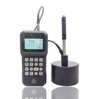
5.3 DHT-200 Hardness Tester
5.3.1 Instrument host
DHT-200 Hardness Tester
 5.3.1 Instrument host
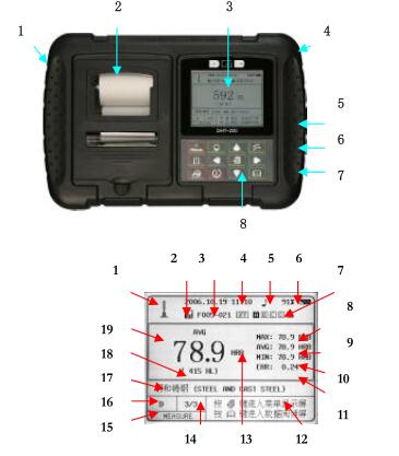
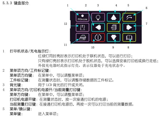
1 Signage
2 Built-in printer
3 LCD monitor
4 Battery compartment/instrument support frame
5 USB port/battery charging port
6 Sensor interface
7 RESET port
8 Keyboard
5.3.2 Display Section
1 Direction of impact
2 Auto-save indicators
3 Storage files currently in use
4 Date and Time
5 Tone indicator
6 Battery level
7 Workpiece markers
8 Measurement data maximum
9 Average of measurement data
10 Measurement data minimum
11 Relative error of measurements
12 Operation Tip Area
13 Hardness system after conversion
14 measurements
15 Measurement Status
16 Sensor Type
17 Measuring Materials
18 Richter measurements
19 Measuring the conversion value
7. Maintenance and repair of instruments
In order to ensure the accuracy and stability of the instrument in long-term use, the status of the instrument should be evaluated, maintained or repaired regularly.
7.1 Maintenance of Rechargeable Batteries
DHT-200 uses four No. 5 rechargeable batteries, and due to the discharge characteristics of the battery itself, it should be guaranteed to be charged regularly to prevent long-termDamage to the rechargeable battery due to non-maintenance. When the instrument is not in use for a long time, remove the battery.
When using an external charger to charge the battery, the charging time should be kept at four to six hours, and it may be charged for too longDamage to the battery, and the charging time is too short to fully charge.
Special note: During the measurement process, if the battery is depleted, you can use four or five alkaline batteries. And due to alkaline electricityThe capacity of the pool may not be able to provide data printing for long periods of time.
7.2 Maintenance of Impact Ball Joints
7.2 Maintenance of Impact Ball Joints
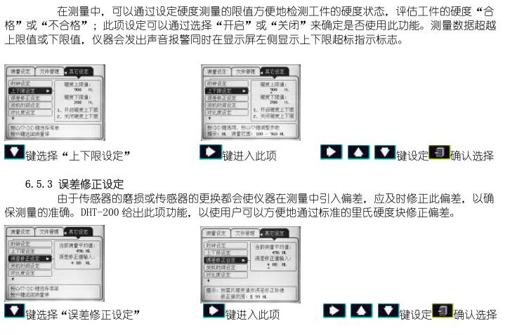
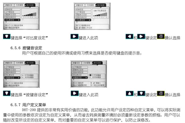
Due to the wear and tear of the impact ball head, the instrument may have a large measurement value or a decrease in the stability of the measurement when measuring. When the measured value is too largeWhen the stability does not decrease, the accuracy of the measurement can be maintained by error correction, which is detailed in "6.5.3 Error Correction Settings".
However, when the measured value is too large and the stability of the measurement is reduced, the only way to contact the manufacturer is to replace the impact ball head.
7.3 Maintenance of impact device cables
In the process of use, there is a possibility that the cable will be damaged, and the instrument will not be able to recognize the impact device and measure it, so it will have to be replacedthis cable.
7.4 Maintenance of Printer Ribbons
As the printing time increases, the printed handwriting will become shallow, broken or even illegible, and the print ribbon should be replaced immediately.The ribbon can be purchased locally or from the manufacturer.
7.5 Warranty of the Instrument
DHT-200 comes with a two-year warranty, users should read the warranty terms and conditions in detail to avoid losing the warranty qualification.

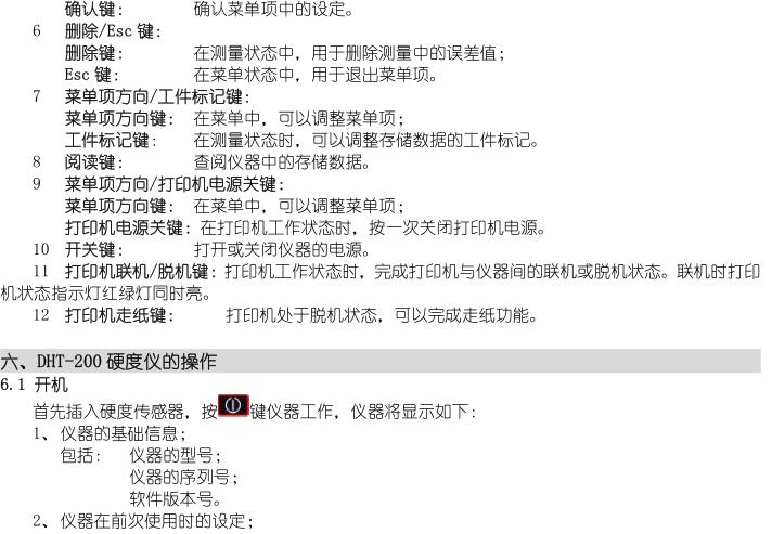
- 1Read the Leeb Hardness Tester in one article
- 2Leeb Hardness Tester different hardness system difference
- 3What products is the Leeb Hardness Tester with D probe suitable for measuring?
- 4Factors Affecting the Accuracy of Leeb Hardness Tester Testing
- 5Leeb Hardness Tester measurement requirements
- 6Factors Affecting the Test Accuracy of Leeb Hardness Tester
- 7What are the measurement requirements for a Leeb Hardness Tester?
- 8What is the Leeb hardness test?
- 9What factors affect the test accuracy, error and repeatability of the Leeb Hardness Tester?
-
![Leeb Hardness Tester AMITTARI AL-150A split Leeb Hardness Tester]()
-
![PRLH150 Leeb Hardness Tester]() PRLH150 Leeb Hardness Tester$ 259.00
PRLH150 Leeb Hardness Tester$ 259.00 -
![Hypertherm LSY-W Leeb Hardness Tester]()
-
![KAIRDA NDT271 Ultrasonic hardness gauge display]()
-
![DUBAN DB22-HM455 Leeb Hardness Tester]()
-
![DUBAN DB22-HM450 Leeb Hardness Tester]()