Discussion and analysis of geogrid tensile performance inspection at different rates

1 Design and procedure of geogrid tensile test
In order to avoid the occurrence of stress concentration caused by specimen slippage in the geogrid tensile test, the joints of the grid are used as clamping positions, and the grids are kept on the same horizontal plane. Both samples adopt the same initial Dimensions, tensile tests were carried out at different tensile rates, and the tensile strength, 2%, 5% elongation strength and elongation, and tensile modulus were recorded.
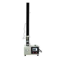
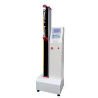
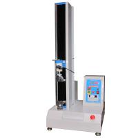
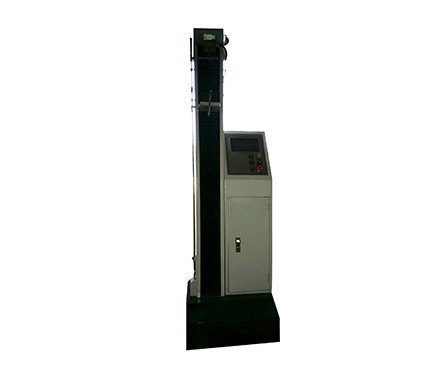
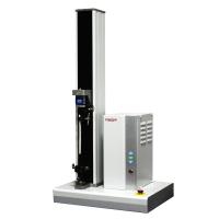
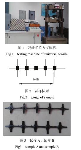
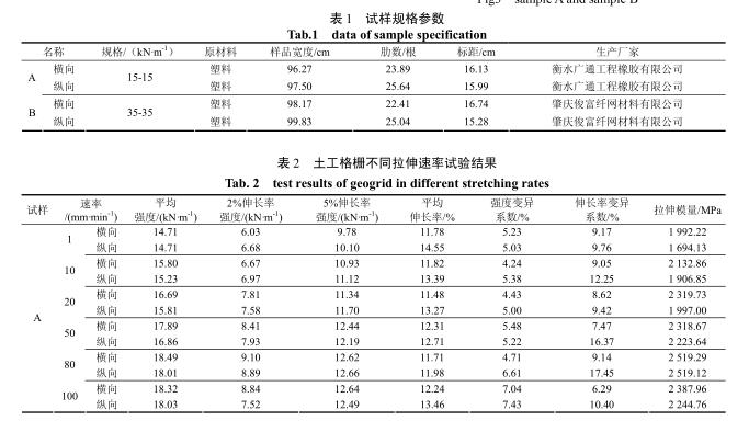
The test instrument adopts a multifunctional Tensile Testing Machine, the model specification UDH_20 is shown in Figure 1; the tensile rate is set as (1, 10, 20, 50, 80, 100)%/min of the clamping length of the sample; the temperature and humidity state is the standard Atmospheric pressure, temperature (23±2)℃, relative humidity (65±5)%, and ensure that the material is placed in this environment for 4 hours; the strip stretching method is used. The relevant data of the material are shown in Table 1. The samples are shown in Figure 2 and Figure 3. (Related instruments: constant temperature and humidity oven)
experiment procedure:
(1) For the cutting of the sample, firstly measure and record the number of grid ribs within a width of 1 m in the horizontal and vertical directions of the whole piece of geogrid, and then cut it with scissors according to a group of 5 nodes. The horizontal and vertical directions cannot be confused. Measure the gauge length of the sample and record it, see Figure 3 Prepare enough samples before the test.
(2) Adjust the temperature and humidity, and place the cut specimens in a specified environment one day in advance for regulation.
(3) Test instrument setting, check whether the instrument is normal, start the instrument and install a suitable test fixture, adjust the distance between the two fixtures to about 150 mm, and use the computer to set the instrument at the required tensile rate.
( 4 ) Clamp the sample, and the clamping position is the nodes on both sides of the sample.
(5) The sample is pre-tensioned, and the clamped test piece is given a pre-tension force of 1% of the maximum load through computer control, and the displacement increment of the test piece produced by the pre-tension force is recorded.
(6) Determine the tensile test, start the testing machine, load the sample until it breaks, return to the initial state after stopping, record the maximum load and the elongation under the maximum load. If the sample breaks within 5 mm from the high jaw, should be easily removed.
2 Geogrid tensile test results
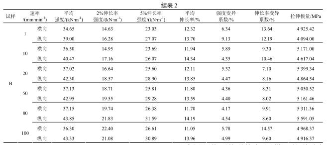
The tensile test results of sample A and sample B are shown in Table 2
3 Geogrid tensile test results
3.1 Relationship between tensile rate and strength
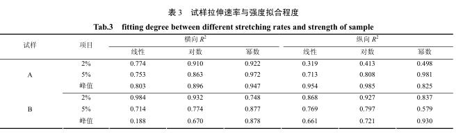
对试样 A和试样 B速率_强度关系分别进行线性、对数和幕数拟合,汇总见表3.由表3可以看出,试样A横纵向2%、5%伸长率强度值和横向峰值强度拟合的 f值从大到小顺序是幕数>对数>线性;而只有纵向峰值拟合的 f 大小顺序是对数>线性>幂数.可以看成是幕数>对数>线性.表示试样 A受拉伸时随速率的增加其强度变化曲线造向子幕数方程.对子试样 B横向5%伸长率强度、峰值强度和纵向峰值强度拟合的 f值大小顺序为幕数>对数>线性;而横向2%伸长率强度拟合 f正好相反;其余纵向2%、5%伸长率强度拟合的 f 由大到小是对数>线性>幕数, 如果只由峰值拟合效果来确定, 那么试样 B拉伸强度同试样A一样都是随着速率的增加强度变化曲线造向子幂函数.
3.2 拉伸速率与伸长率关系
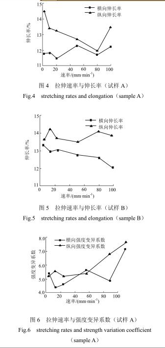
试样 A和试样 B拉伸速率与伸长率关系见图4、图5,可以看出,试样 A纵向波动比较大些, 在低速率时伸长率略高,当速率达到80mm/min时最低,而横向波动并不算大;拉伸速率的变化对子试样 B 横向和纵向伸长率变化无显著的影响.试样A和试样 B共同的特点就是其纵向伸长率要普遍高子横向伸长率值, 这种结果是因为双向土工格栅生产工艺所造成的.
3.3 拉伸速率与变异系数关系
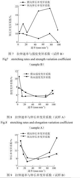
试样A和试样B拉伸速率与变异系数关系件图6~图9.试样 A当速率较高时显示出强度变异系数值偏大,速率在10~20 mm/min范围内强度变异系数最低;试样 B则是在速率低时强度变异系数值较大, 在10~80 mm/min范围内低,并且波动很小,而速率从80m m/min后强度变异系数又有增加造势.因此,有强度变异系数知,土工格栅不同拉伸速率试验数据重演性更好是在10~50 mm/min范围内.
It can be seen from Figure 8 and Figure 9 that the longitudinal variation coefficient rate of sample A is lower before 50 mm/min than after 50 mm/min, while the overall horizontal fluctuation is not large, and the lowest point appears at 50 mm/min; The coefficient of variation of transverse and longitudinal elongation of sample B is the lowest within 20-50 mm/min, and increases significantly after the speed is small at 20 mm/min and the speed is large at 50 mm/min. In other words, considering the test data as a whole, the repeatability range is 20-50 mm/min.
3.4 Relationship between tensile rate and tensile modulus
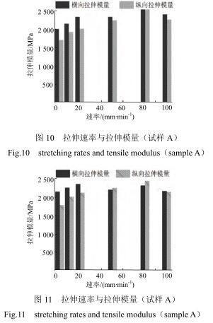
By drawing Figure 10 and Figure 11 in Table 2, it can be seen that the tensile modulus of sample A and sample B gradually increases with the increase of the tensile rate, but after reaching 80mm/min, a downward momentum appears; sample A and sample B The highest tensile modulus of B is 32.75% and 26.78% greater than the lowest tensile modulus; the transverse tensile modulus value in sample A is greater than the longitudinal tensile modulus value, while the low tensile rate in sample B The tensile modulus in the transverse direction is relatively large at high tensile rates, and the tensile modulus in the longitudinal direction is relatively large at high tensile rates. The tensile modulus of sample B is much larger than that of sub-A because the specification of B is larger than that of sub-A.
4 Conclusion
(1) With the increase of the tensile rate, the strength and peak strength of the geogrid at 2% and 5% elongation are all directed to the sub-curtain function curve; the elongation is not significantly affected by the speed;
( 2 ) The tensile modulus of geogrid increases gradually with the increase of the tensile rate, but it declines after reaching 80 mm/min;
(3) In specific engineering applications, it is necessary to select an appropriate tensile rate to meet the required and appropriate tensile modulus in the project;