What does electro-coating equipment include?
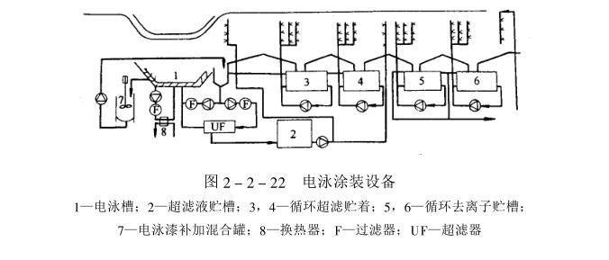
Electrophoretic coating equipment is composed of electrophoretic disinfection, standby disinfection, circulation filter system, ultrafiltration system, anode liquid circulation system, heat exchange system, DC power supply, paint replenishing device, flushing system and control cabinet, etc. (see Figure 2 -2-22).
(1) Electrophoretic elimination
For the continuous passing type, a boat-shaped noise is used, and for the step-by-step type, a rectangular shape is used. No matter what kind of tank it is, there must be no dead angle, so the rounded corners at the bottom of the tank transition. The volume of the launder is 1/10 of that of the main tank, and the drop of the liquid level is controlled within 150mm to avoid excessive foam. In addition, a filter can be erected to eliminate foam and impurities from the main tank. For the cathode electrophoresis tank, due to The paint liquid is an acidic medium, and it should be anti-corrosion and insulated with 2~3mm FRP lining, and the withstand voltage should be above 15ooov. The spare tank is used for cleaning the main tank and storing the tank liquid during maintenance, and general anti-corrosion measures are sufficient.
(2) Circulatory system
The function of the circulation system is to ensure the uniform composition of the bath liquid and good dispersion stability. In addition, it is used to filter impurities, heat exchange and eliminate air bubbles generated by electrolysis at the interface of the workpiece. Usually, the combination of filtration cycle, filtration heat exchange cycle and ultrafiltration cycle is adopted. To achieve the above functions, in order to prevent the paint liquid from settling, the flow velocity of the tank bottom and the circulation pipe should be above 0.4m/s; The precision of the filter bag set in the pipeline is 50µm, and it is also required to filter with a filter bag before ultrafiltration. The setting of the valve in the pipeline and the bypass should consider avoiding dead ends to prevent the paint liquid from settling and producing particles.
(3) Electrode device
The electrode device is composed of a pole plate, a diaphragm and an auxiliary electrode. Anodic electrophoresis can use ordinary materials as the pole plate, and cathodic electrophoresis needs to use stainless steel, graphite or titanium alloy materials as the positive plate. The area ratio of the pole plate to the workpiece is 1 for the anode electrophoresis. : 1. Cathodic electrophoresis is 1:4. During the process of electrophoretic painting, the bath liquid at the electrode interface has the following changes.
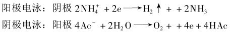
In order to prevent the acid or alkaline electrolyte produced by electrolysis from diffusing in the bath, it is necessary to use a semi-permeable membrane as a diaphragm to control the pH value of the bath. In the diaphragm, the electrolyte is continuously enriched, and it can be discharged by discharging the polar liquid. Control the concentration of bath electrolyte. In order to keep the concentration of polar liquid constant, the polar liquid should be circulated at 6~10L/min·m2 (plate).
(4) Power supply current
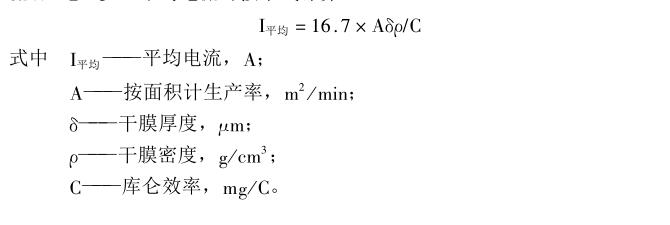
When electrophoretic painting, from the perspective of operational safety, the workpiece is grounded. The electrification method of the workpiece, for the continuous passing type, adopts electrification into the slot and boosts the voltage in two or three stages, and the current of the DC power supply is the average current x (1.5~2); the step-by-step production mode adopts electrification after entering the slot, and gradually increases the voltage. For example, it rises to the low working voltage in 10~15s, and then rises to the normal working voltage. The current of the DC power supply is the average current x(2~3). The average current can be calculated as follows:
(5) Addition of electrophoretic paint
The electrophoretic paint is added in the mixing tank, and the original paint is diluted with the tank solution under stirring, and then sent to the electrophoresis tank after mixing evenly. A mixer can also be set in the circulation pipeline for continuous supplementation.
(6) flushing system
After the electrophoretic coating comes out of the tank, immediately rinse the tank with fresh ultrafiltrate, rinse with fresh ultrafiltrate after 1-2 times of circulating ultrafiltrate, and finally rinse with decontaminated water.
The ultrafiltration capacity of the ultrafilter is calculated as follows:
Q=(1.03~1.04)x(1.2_1.5)L/m2(workpiece)
The ultrafiltrate storage tank should be able to hold the amount of ultrafiltrate for at least 3h flushing. Once the flow rate of the ultrafilter drops below 70%, it should be cleaned, so there should be another set for ultrafiltration.
(7) Debugging of electrophoretic coating equipment
1. Equipment cleaning
Add water for equipment function debugging 1. Add surfactant and 0.2% co-solvent, cycle cleaning for 8~20h→drain→add water and cycle for 2~8h, twice in total→check that there is no oil (especially inside the valve)→add and remove Water circulation for 2~8h, measured electrical conductivity <25ttm/Cia, and after the small sample is mixed with paint and the coating film has no shrinkage cavity, it can be used to match the tank.
2. Slot matching
Close the ultrafiltration system → add electrophoretic paint, add pure water, add regulator → cycle for 2~3 hours → check solid content, ash content, MEQ, pH and coating appearance → adjust the temperature of the tank solution → adjust the electrode solution + start the ultrafilter →Adjust flushing system.
3. Trial coating
After the newly prepared bath liquid is matured for 48 hours → apply voltage → check voltage → current → after the time relationship is normal, after the liquid flow is suitable → check the flushing system → dry, check the appearance of the dry film, the uniform thickness of the film and the coating status of the inner cavity .
- 1Regulation and maintenance of lame plating equipment
- 2How to choose car lame plating equipment?
- 3Introduction to the principle and characteristics of lame plating
- 4Electrophoresis painting equipment process introduction
- 5Summary of high pressure airless spraying tools and construction methods
- 6Painting equipment performance acceptance project
- 7Manufacturing, construction and acceptance of painting equipment
- 8Precautions for acceptance of painting projects