NDJ-79 swirl/spin Viscometer Operation Application Instructions
NDJ-79 rotary viscometer is a precision instrument for measuring the absolute viscosity of various Newtonian liquids and the apparent viscosity of non-Newtonian liquids. If used with a specific rotor, it can also determine the rheological properties of non-Newtonian liquids. It has the advantages of convenient use, stable performance, and simple maintenance. It is suitable for measuring various oils, paints, inks, coatings, plastics, slurries, rubber, latex, detergents, resins, condensed milk, cream, drugs, and cosmetics. The viscosity of the fluid is a necessary instrument for the laboratories and analysis rooms of textile, chemical, petroleum, electromechanical, pharmaceutical, food, light industry, construction, and other industries, as well as universities and colleges, scientific research units, and military departments.
How the instrument works
The instrument is driven by a miniature synchronous motor, which rotates at a constant speed of 750r/min, and is hardly affected by changes in load and power supply voltage. The housing of the motor is installed in a suspended manner. It drives the rotating drum to rotate through the rotating shaft. When the rotating drum rotates in the liquid to be measured, it is subjected to viscous resistance, thereby generating a reaction force that deflects the motor housing. The motor housing is connected to two The positive and negative metal balance springs are connected, and the rotation of the case causes the balance springs to generate torque. When the torque of the balance spring and the viscous resistance torque are balanced, the pointer connected to the motor case will point out a certain value on the dial, which is proportional to the viscous resistance of the drum, so the scale reading is multiplied by the rotation The barrel factor represents the magnitude of the dynamic viscosity.
test unit
NDJ-79 rotary viscometer is attached with two kinds of test units, each unit includes a measuring container and several rotating cylinders with rotating shafts.
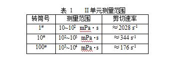
The second unit has three cylindrical drums (1”, 10”, 100”), specially treated brass tubes, 1” is the thickest, and 100” is the thinnest. There is a water barrier in the measuring container. Constant temperature water can be passed through. There are two screw holes on the upper part of the measuring container, one is used to insert a bimetallic thermometer, the other is sealed with a screw plug, and a glass thermometer with a suitable seal can also be inserted (but not provided by this unit). Hanging The drum is a left-handed knurled nut with a hook.
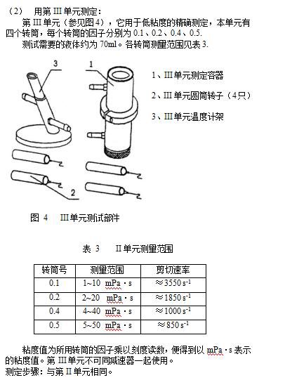
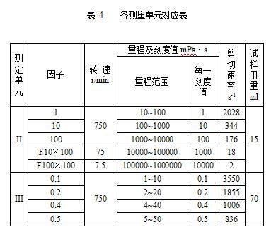
The third unit has four cylindrical drums (0.1", 0.2", 0.4", 0.5"), specially treated brass tubes, 0.1" is the thickest, and 0.5" is the thinnest. There is a long cylinder with a water-proof jacket inside the measurement container, and a special bracket for installing a bimetallic thermometer. The constant temperature water flows through the bracket first, and then flows into the measurement container of unit III. The bimetallic thermometer and hook knurled nut are shared with the second unit.
Instructions for use
2. Power supply
The power supply voltage of this viscometer is 220V, the frequency is 50Hz AC, and the voltage drop in the instrument is (24V~30V) after the transformation. When the instrument is powered on, the power cord is first connected to the instrument and then plugged into the power socket.
3. Left-handed knurled nut (anti-thread) connection
Units II and III use left-handed knurled nuts with hooks. When dismounting the left-handed knurled nut, insert a thin rod with a diameter of 3mm into the small hole on the side of the bakelite disc, so that the motor shaft is stuck, which makes it easy to screw on or remove the left-handed knurled nut.
4. Zero point correction (zero adjustment)
When the viscometer leaves the factory after debugging and verification, the position of the pointer should be between 5 and 10 grids. When zeroing, the motor should be rotated without load, and the zeroing screw should be screwed in gently, and the pointer will slowly return to zero at this time. If the pointer has returned to the zero point, the zero adjustment screw cannot be screwed in again. At this time, it should be unscrewed in the opposite direction, otherwise the zero adjustment spring is easy to break, please pay attention. The zero point calibration during the test should be repeated three times under no-load when the machine is turned on, and the zero point is confirmed to be correct, and then the zero point adjustment is completed and the test can be carried out. After the test, the zero adjustment screw should be withdrawn.
5. Connection of drum
The rotating elements of units II and III are attached with steel wire shaft hooks, and the motor transmits the torque to the rotating drum through the hook shafts. This method is used to avoid twisting the hooks.
The drums of units II and III are connected to the rotating shaft through the U-shaped spring that has been located in the drum. The hook shaft pulls out the U-shaped spring from the drum to remove the drum. When reinstalling the drum, it should be The two ends of spring stretch to get final product in the barrel.
Each unit test method:
(1) Determination of Unit II
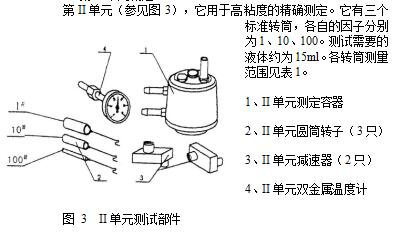
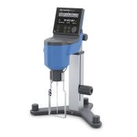
The viscometer multiplies the scale reading by the factor of the drum used, and the viscosity value expressed in mPa·s can be obtained.
Test steps:
Pour the liquid to be tested into the test container carefully until the liquid level reaches the edge of the conical face, then insert the rotating cylinder into the liquid until it is completely submerged, then place the test container on the instrument bracket, and hang the rotating cylinder hook on the instrument on the hook of the left-hand knurled nut. At this time, start the motor, and the drum rotates and shakes from the beginning to the center. To speed up the centering, the Tester can be moved back and forth, left and right on the bracket slightly, and the reading can be read when the pointer is stable. If the reading is less than 10 divisions, replace the drum with a larger diameter.
Determination using a reducer:
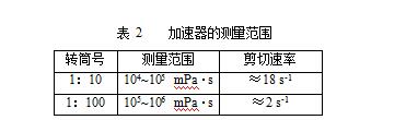
When measuring high-viscosity solutions (more than 10000mPa·s) with the second unit, two reducers can be used as additional devices, and the speed ratios are 1:10 and 1:100. At this time, the rotation speed of the drum is reduced accordingly. It is 1/10 and 1/100 of the original value, that is, the speed is reduced to 75r/min and 7.5r/min.
The factors of 1:10 and 1:100 reducers are 10 and 100 respectively, and they are only applicable to the drum with a factor of 100, the thinnest 100#. The measuring range is shown in Table 2.
The calculation of the viscosity value after using the reducer: that is, the factor of the drum is multiplied by the factor of the reducer and then multiplied by the scale reading to obtain the viscosity value in mPa·s.
Installation and fixing of reducer:
Insert the coupling at the input end of the reducer into the motor input shaft, and mesh with the coupling on the input shaft of the motor, and fix the reducer at the end of the thin rod through knurled bolts (the thin rod is located behind the motor shaft and goes downward protruding), tighten the bolts so that the reducer is just in a horizontal position. Then screw the left-handed knurled nut on the output shaft and readjust the zero point.
Precautions
1. This viscometer is a precision testing instrument. Please read this manual carefully before use. During use and maintenance, you must strictly abide by the conditions and steps specified in the manual.
2. The instrument needs to be used within the specified voltage (220V±10%) and frequency (50Hz), otherwise the speed and measurement accuracy will be affected. If the grid frequency is not 50Hz, the actual viscosity needs to be obtained according to the following correction formula.
3. The power cord needs to be plugged into the instrument first and then powered on.
4. After turning on the start switch of the motor, if the motor fails to start in time, the switch should be turned off immediately and restarted.
5. The motor should not be used continuously for a long time, generally not more than 4 hours.
6. The instrument has been debugged and calibrated and verified by the metrology department before leaving the factory. Therefore, the internal parts of the instrument are not allowed to be disassembled at will, and the balance spring is strictly prohibited.
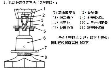
7. When the instrument leaves the factory, the agate bearing should not be shattered during transportation, so it is equipped with a shock absorber, which can be removed when it is used.
8. Before and after use, the drum and the inner wall of the measuring device should be cleaned and dried to ensure the measurement accuracy of the instrument. The U-shaped spring hanging rings of the rotors of the II and III measuring units can be pulled out to clean the inside and outside of the rotors, and then insert the springs.
9. Do not use too much force when disassembling the coupling, insert the insert rod first, and then install and disassemble the counter-tooth knurled nut.
10. The instrument should always be kept dry when stored.
- 1Rotational viscometer - principle, classification, application and calibrating
- 2Application of NDJ-8S digital Rotational Viscometer in viscosity measurement of cosmetic raw materials
- 3NDJ-5S digital Rotational Viscometer accurate measurement of natural oil viscosity
- 4Application of SNB-1 + L0 digital swirl/spin Viscometer in Oil Industry
- 5Application of HBDV-1H swirl/spin High Temperature Viscometer in Viscosity Determination of Plastic Particles
- 6Rotational viscometer selection guide: How to choose the right viscosity equipment for you?
- 7Principle, type and accuracy control of Rotational Viscometer
- 8Which Viscometer to Choose for Licorice Extract Viscosity Testing? How to Test?
- 9Application of Rotational viscometer in Waterborne Polyurethane Adhesive


