GB/T13452.2-2008 Determination of film thickness of Paints and varnishes [text version]
1 Scope
This section specifies a range of methods for measuring coatings applied to substrates, including methods for measuring wet film thickness (recommended instrument: wet Film Thickness Gauge), dry film thickness, uncured powder coating thickness, and paint film thickness on rough surfaces. Where a test method standard exists, this section refers directly to those standards, otherwise the test method is described in detail.
Appendix A provides an overview of the test methods, specifying the scope of application, existing standards, and precision for each test method.
Terms related to varnish thickness measurement are also defined in this section.
2 Normative references
The terms in the following documents are incorporated into this part by reference in this part of GB/T13452. All subsequent amendments (excluding errata) or revisions to dated references are not applicable to this Part, however, parties to agreements under this Part are encouraged to explore the possibility of using new versions of these documents. For undated references, a new version of the document applies to this section.
ISO 463 Technical Specification for Geometric Quantities (GPS) Dimensional Gages Design and metrological characteristics of mechanical dial indicators
ISO 3611 Spiral Micrometer for Measuring External Dimensions
ISO 4618:2006 Pigments and varnishes Terms and definitions
SIO 8503-1 Pretreatment of Steels Prior to Painting and Related Products Surface Roughness Characteristics of Spray Cleaned Steels Part 1: Technical Requirements and Definitions for ISO Comparison Blocks for Evaluating Surface Roughness for Abrasive Jet Cleaning.
3 Terms and Definitions
The terms and definitions identified in ISO 4618:2006 and the following apply to:
3.1Substrate
Surfaces to which paint has been applied or is about to be applied
[ISO 4618:2006]
3.2Coating coating
A continuous layer formed after the paint has been applied to the substrate in one or more passes
[ISO 4618:2006]
3.3Film thickness
The distance between the surface of the paint film and the surface of the substrate
3.4wet-film thickness
The thickness of the freshly applied wet film coating is measured immediately after the paint is applied
3.5Dry-film thickness
The thickness of the coating that remains on the surface after the paint has hardened
3.6Thickness of uncured powder layer
The thickness of the freshly applied powder coating is measured immediately after the powder coating is applied and before baking
3.7Relevant surface area
The part of the surface of the object that is covered or about to be covered by a coating that is necessary for the object to be durable and/or to have a beautiful appearance
3.8Test area
A representative portion of the relevant surface area in which an agreed number of single measurements is taken as a spot check
3.9Measurement area
The area where a single measurement was taken
3.10minimum local film thickness
The lowest value of the local paint film thickness found in the relevant surface area of a particular specimen
3.11maximum local film thickness
The highest value of the local paint film thickness found in the relevant surface area of a particular specimen
3.12Mean film thickness
All individual paint thickness measurements in the specimen area are worth the arithmetic mean or gravimetric analysis of the paint thickness results
3.13Calibration
Measure the controlled and documented process of traceable calibration standards and ensure that the results are within the specified accuracy range of the measuring instrument. Note: Initial calibration is typically performed by the instrument manufacturer or a qualified laboratory using documented methods in a controlled environment. The user then checks the results of the initial calibration at specified intervals. The resultant uncertainty of the measurement results obtained using the calibration standard is lower than the specified accuracy of the instrument.
3.14Verification
An accuracy check carried out by the user using a reference standard
3.15reference standard
The accuracy of the measuring instrument can be verified by comparing the thickness values of the specimens with known thicknesses.
Note: The reference standard can be a painted thickness or sheet, and if agreed by the contracting parties, a certain part of the specimen may be used as the thickness standard for special work.
3.16Adjustment
The operation of aligning the thickness readings of the measuring instrument with the thickness values of the participating reference standards
Note: When the thickness of the coating or sheet is known, most electrical measuring instruments can be adjusted on a thickness standard or sheet.
3.17Accuracy
The consistency between the measured and true values of the thickness standard.
4. Determination of wet film thickness
4.1 General
Appendix A gives an overview of the method for measuring wet film thickness.
4.2 Mechanical Law
4.2.1 Principle
In all mechanical test methods, one part of the test instrument is in contact with the substrate surface through the coating, and the other part of the instrument is in contact with the coating surface at the same time (see Figure 1), or subsequently with the coating surface (see Figures 2 and 3). The wet film thickness is the height difference between the two contact points, which can be read directly.
4.2.2 Scope of application
The mechanical principle applies to all varnishes. Substrate combinations. In the test area, the substrate should be flat in at least one direction. Allows bending on a surface (such as the inner or outer surface of a pipe).
4.2.3 General
Test methods are classified as destructive and non-destructive, and their classification depends on the following factors:
a) flow deformation of the paint;
b) the nature of the wet contact between the contact surface of the test instrument and the paint;
c) Whether the thickness measurement will make the coating unfit for its intended use.
Since it cannot be ruled out that pigment particles remain between the instrument and the substrate, all mechanical test methods contain a systematic error: the paint film thickness shown is at least one average diameter of the pigment particles lower than the actual wet film thickness.
When using wheel gauge (see 4.2.5 Method 1B), the wheels need to be wetted with paint. If it is not wetted, this will mean that further systematic error will be introduced, resulting in a large reading, which is the result of a combination of the following factors:
- surface tension and rheology of coatings;
- the material of the wheel gauge;
- The speed at which the wheels turn.
4.2.4 Method 1A – Comb gauge
4.2.4.1 Instrument description
A comb gauge is a flat plate made of corrosion-resistant material with a series of tooths arranged on its edges (see Figure 1). The reference teeth at the corners of the plate form a baseline, and the internal teeth arranged along this baseline form a progressive gap series between the reference teeth. Each tooth is indicated with a given clearance depth value.
The maximum thickness of the comb gauge that can be purchased on the market is generally 2000 μm, and the minimum increment is generally 5 μm.
4.2.4.2 Steps
Make sure the tooth is clean and not worn or damaged. Place the comb gauge on a flat surface of the specimen so that the tooth is perpendicular to the specimen surface. There should be enough time for the paint to wet the tooth and then remove the comb gauge.
If one side of the specimen is bent, the comb gauge should be placed parallel to the axis of the bent surface.
Thickness measurements are time-dependent, so thickness should be measured as soon as possible after the paint is applied.
The maximum clearance depth reading of the internal teeth wetted by the paint is recorded as the wet film thickness.
4.2.5 Method 1B – Wheel gauge
4.2.5.1 Instrument description
The wheel gauge is constructed of a wheel made of corrosion-resistant hardened steel with three raised rims (see Fig. 2).
The rim has the same diameter and the shaft of the wheel is mounted on the same axis. The third rim has a smaller diameter and is eccentricly mounted. There is a scale on the outer rim from which the distance from the concentric flange protrusion relative to the eccentric rim can be read.
Two models:
- Model 1, where the eccentric rim is located between two concentric rims;
- Model 2 where the eccentric flange is located outside and immediately adjacent to one of the two concentric flanges.
Note: Unlike Model 1, Model 2 is designed so that there is no parallax for wet film thickness readings.
The maximum thickness that can be measured by the wheel gauge available on the market is generally 1500 μm, and the minimum increment is generally 2 μm.
4.2.5.2 Steps
Hold the wheel gauge by holding the axle between your thumb and forefinger and press the concentric rim against the surface by touching the surface where the maximum reading on the scale is located.
If one side of the specimen is bent, the shaft of the wheel gauge should be parallel to the shaft of that bending.
Roll the wheel gauge in one direction and then pick it up from the surface to get the maximum scale reading of the eccentric rim that can still be wetted by the paint. Wash the wheel gauge and repeat this step from the other direction.
The wet film thickness is calculated using the arithmetic mean of these readings.
Thickness measurements are time-dependent, so thickness should be measured as soon as possible after the paint is applied.
To reduce the effect of surface tension on the results, observe how the paint wets the eccentric rim and record a scale reading at the first point of contact. This is only possible with the wheel gauge of Model 2
4.2.6 Method 1C – dial gauge
4.2.6.1 Dial gauge (see Figure 3)
ISO 463 compliant mechanical dial gauges and electronic dial gauges can achieve measurement accuracy of 5 μm (mechanical dial gauge) and 1 μm (electronic dial gauge), or better. The dial indicator has either an analog or digital display function.
On the underside of the dial gauge there are two contact feet of the same length, arranged equidistant from the active punch bar, and in the same straight line as the punch bar. The adjustment screw fine-tunes the position of the punch bar in the rail.
4.2.6.1.2 Reference standard for dial indicator zeroing
It is required to use a flat reference plate for the zeroing of the dial gauge. The reference plate consists of a flat glass plate with an unevenness tolerance of no more than 1 μm (see also ISO 110).
4.2.6.2 Steps
Zero the dial gauge on the reference plate and adjust the measuring contacts so that they are just in contact with the plate.
Turn the punch back from the zero position. Place the contact foot of the dial gauge perpendicular to the surface of the substrate on the specimen and carefully unscrew the punch bar so that the measuring contact is in contact with the paint.
Thickness measurements are time-dependent, so thickness should be measured as soon as possible after the paint is applied.
Read the wet film thickness directly from the scale.
4.3 Gravimetric analysis
4.3.1 Principle
When applying paint, the wet film thickness is obtained by dividing the quality of the applied paint by the density of the paint and the surface area of the coating.
where:
m0 - the mass of the unpainted specimen, in grams (g);
m - the quality of the painted style, in grams (g);
A - the surface area of the coating, in square meters (㎡);
P – density of the liquid coating applied in grams per milliliter (g/mL)
Note: The density of the applied liquid paint can be determined according to the provisions of GB/T 6750, ISO 2811-2 or ISO 2811-4.
4.3.2 Scope of Use
As long as the amount of highly volatile substances in liquid coatings is small, gravimetric analysis principles are usually applicable.
4.3.3 General
The average value of the wet film thickness over the entire application area measured using the gravimetric principle. In particular, when applying by spraying, the back side of the specimen should be covered to avoid measurement errors due to partial coating (spillage) on the back side. Before weighing the painted specimen, any masking on the back of the specimen should be removed.
4.3.4 Method 2 - Differential quality issuance
4.3.4.1 Instruments
The maximum weighing range of the balance is required to be 500g with an accuracy of 1mg.
4.3.4.2 Steps
The mass of the unpainted specimen is weighed first, and then the mass of the painted specimen is weighed, and the wet film thickness is calculated according to Eq. (1).
4.4 Photothermal method
4.4.1 Principle
The paint film thickness is determined by measuring the time difference between the heat wave radiating to the coating and the returning wave, which can be both thermal and ultrasonic waves (see Figure 4).
Regardless of the excitation or inspection method, all photothermal methods have the same principle: i.e., periodic or pulsing energy is applied to the specimen in the form of heat, and then the local temperature increase is checked.
The paint film thickness is obtained by comparing the time difference measured on the specimen with the value measured on a film of known thickness under fixed conditions (excitation energy, pulse length, excitation frequency, etc.) using the same instrument (see 4.4.4.2).
4.4.2 Scope of application
The photothermal principle is applicable to almost all film-substrate combinations. This method can also be used to determine the thickness of individual coatings, as long as the coatings in a multi-coat system are well distinguished from each other in terms of thermal conductivity and radioactivity.
The minimum substrate thickness required varies depending on the measuring system used (see 4.4.4.1.1) and the varnish-substrate combination.
4.4.3 General
Test methods are classified as destructive and non-destructive, and their classification depends on the purpose of the coating. Due to the local thermal effects of production, the absorption of heat energy by the coating may have an effect on the coating (see Figure 4 in 8).
4.4.4 Method 3 – Determination of thermal properties
4.4.4.1 Instruments and reference standards
4.4.4.1.1 Measurement systems
There are a number of methods in which the coating material can generate thermal waves and the thermal effects of the heated part of the test specimen (see EN 15042-2). Thermal radiation sources (e.g., laser sources, light-emitting diodes, incandescent light sources) are primarily used as excitation systems for coatings.
The following assays are available:
- detection of the returned thermal radiation (photothermal radiation measurement);
- detection of changes in the refractive index (hot air measurement above the measurement area);
- Hot spot detection (measurement of heat flow);
4.4.4.1.2 Reference standards
Calibration requires reference standards with different absorption properties and different film thickness ranges (see EN 15042-2).
4.4.4.2 Calibration
For each film-substrate combination (especially for each coating), calibrate the measuring system with a reference standard (see 4.4.4.1.2).
4.4.4.3 Steps
Operate the instrument and measure the paint film thickness according to the manufacturer's instructions.
5 Determination of dry film thickness
5.1 General
Appendix A gives an overview of the method for determining dry film thickness.
5.2 Mechanical Law
5.2.1 Principle
Use a micrometer or dial gauge (see 5.2.4 Method 4A) to measure the thickness of the paint film, i.e. the difference between the total thickness of the substrate and the thickness of the substrate.
There are two ways to determine the thickness of the paint film:
a) Measurement before and after coating removal (destructive method)
The total thickness of the specified area is measured first, and then the thickness of the measurement substrate is measured after the coating in the measurement area is removed.
b) Measurement before and after coating application (non-destructive method)
The thickness of the substrate is measured first, and then the total thickness of the same measuring area is determined after the paint has been applied.
The varnish thickness can be calculated from the difference between the two readings.
A depth gauge (see 5.2.5 Method 4B) or a surface profiler (see 5.2.6 Method 4C) can directly measure the paint film thickness, i.e. the height difference between the paint film surface and the exposed substrate surface.
Note: Only the "Coating Removed" measurement method can be determined using a depth gauge or a surface profiler (Method 4B and Method 4C).
5.2.2 Scope of application
The mechanical principle is basically applicable to all film-substrate combinations. When measuring with a mechanical instrument, the substrate and varnish should be hard enough to avoid indentations in the measurement contacts that can lead to erroneous readings.
Micrometers or dial gauges (Method 4A) are also suitable for measuring the thickness of paint films in the form of cylindrical ones with circular cross-sections (e.g. wires, pipes).
In the event of a dispute, the Surface Profile Scanner (Method 4C) is the method of arbitration.
5.2.3 General
In the "applied coating" method, a sample gauge with marked holes is used to ensure that the substrate thickness and the total thickness are measured at the same point.
Note 1: In the case of plastic substrates, the "apply coating" method is recommended, as in most cases it is difficult to expose the substrate without causing damage.
In the "Remove Coating" measurement method, you can draw a circle and mark the measurement area. The coating of the measuring area should be removed carefully and completely without causing mechanical or chemical damage to the substrate. Before applying the paint, the substrate can be partially covered with adhesive tape to obtain a well-defined layer from one layer to another.
When using a depth gauge or a surface profile scanner (Method 4B and Method 4C), the unremoved coating from the measurement area should remain intact. With a surface profile scanner (Method 40C), it should be possible to determine the protrusions between the substrate and the surface of the paint film.
For hard substrates (e.g. glass), the coating can be removed mechanically; However, for sub-hard substrates (e.g. steel plates), the coating can be removed by chemical methods, such as solvents or paint strippers.
Note 2: For sub-hard substrates, such as steel plates, a hollow drill with a diameter of 10 claws can be used to cut through the paint film, and then the original coating sheet formed is removed with solvent or paint remover.
All surfaces that need to be touched or measured (coatings, substrates, backsides of the specimen) should be clean and free of minimum residues.
5.2.4 Method 4A – Thickness Difference Method
5.2.4.1 Instrument description
5.2.4.1.1 Micrometer
The micrometer should be accurate to 5 μm. The micrometer should be equipped with a toothed bar to limit the force exerted by the measuring rod on the test surface.
Model 1 – Attached to the pedestal
One end of the micrometer with a flat measuring surface is clamped to a rigid base with a flat substrate so that its height is adjustable. The measuring surface is aligned parallel to the upper surface of the substrate.
Model 2 – Hand Hold (see Figure 5)
The common name for this type of instrument is a wildcard gauge micrometer, although it is also known as a spiral micrometer for measuring external dimensions (ISO 3611 ISO3611). The measuring surface and datum of the measuring rod should be flat and parallel to each other.
5.2.4.1.2 Dial gauges
ISO 463 compliant mechanical dial gauges and electronic dial gauges typically have a measurement accuracy of 5 μm (mechanical dial gauge) and 1 μm (electronic dial gauge), respectively, or better. The dial indicator should be equipped with a device that can pick up the measuring contacts. The shape of the measurement contacts should be selected according to the hardness of the coating material with the test thickness (spherical for hard materials and flat for soft materials).
Model – fixed to the pedestal
The dial gauge is clamped to the base as shown in Figure 6. If you make a planar measuring contact, the measuring surface is aligned parallel to the upper surface of the substrate.
Model 2 – Hand-held
This type of dial indicator should be equipped with a handle. The device used to lift the punch bar should be shaped so that the thickness Tester can be operated with one hand. The detachable contact of the datum plane should be located opposite the translationable measuring contact. The shape of the measuring contacts should be selected according to the hardness of the material to be measured (spherical for hard materials and flat for soft materials).
If both the measuring contact and the datum are planar (as shown in Figure 7 for measuring the thickness of a lamella), the measuring surfaces should be parallel to each other.
5.2.4.2 Steps
According to the provisions of 5.2.3, prepare samples for different measurement methods of "removing coating" and "applying coating" (see 5.2.1).
When using the different measurement methods of "removing the coating" or "applying the coating", the painted or painted side of the specimen should be operated in such a way that the painted side of the specimen or the surface to be painted is facing the measuring rod (micrometer, see 5.2.4.1.1) or the contact element (dial gauge, see 5.2.4.1.2), respectively.
When using the instrument fixed to the base (Model 1 in 5.2.4.1.1 and 5.2.4.1.2), place the specimen on the substrate.
When using a hand-held instrument (Model 2 in 5.2.4.1.1 and 5.2.4.1.2), hold the specimen against the fixed measuring contact and hold the specimen.
Note: The handle of the instrument specified in Model 2 in 5.2.4.1.1 and 5.2.4.1.2 can also be clamped to the base for easier operation.
Repeat the above steps for the second measurement after removing the paint film ("Paint Removal" method) or applying the paint film ("Paint Application" method).
Take each measurement as follows:
——When using the micrometer as described in 5.2.4.1.1, move the measuring rod to the surface to be measured until the tooth bar is touched;
- When using the dial gauge described in 5.2.4.1.2, make the contact of the contact element equipped with a spring lightly touch the test surface.
The varnish thickness value is the difference between the total thickness reading and the substrate reading.
5.2.5 Method 4B – Depth gauge
5.2.5.1 Instruments and reference standards
5.2.5.1.1 Model 1 – Depth gauge micrometer (see Figure 8)
This type of micrometer typically has a measurement accuracy of 5 μm or better. The micrometer should be equipped with a tooth bar to limit the force exerted by the contact element on the substrate and should have a flat base or foot to rest on the painted surface as a reference plane.
5.2.5.1.2 Model 2 – depth dial indicator (see Figure 9)
ISO 463-compliant mechanical dial gauges and electronic dial gauges typically have measurement accuracy of 5 μm (mechanical dial gauge) and 1 μm (electronic dial gauge), respectively, or better. The dial indicator should have a flat base or feet to rest on the painted surface as a reference plane.
5.2.5.1.3 Used as a reference standard for instrument zeroing
A flat reference plate is required to zero the instrument. The reference plate is a flat glass plate with an unevenness tolerance of no more than 1 μm (see also ISO 1101).
5.2.5.2 Steps
Remove the coating from the measurement area. By checking the zero point of the instrument with a reference plate (5.2.5.1.3) and zeroing it, then:
a) After using the depth micrometer, place the feet on the surface of the coating so that the measuring rod is above the exposed area, and rotate the measuring rod downward until the contacts touch the substrate and touch the shank;
b) When using a depth dial indicator, place the contact element above the exposed substrate with its contact feet on the coating (if the dial indicator has contact foot types, care should be taken to ensure that the contact feet are perpendicular to the specimen surface).
Film thickness values can be read directly from depth readings (with zero error calibration if required).
5.2.6 Method 4C – Surface Profile Scanning
5.2.6.1 Instrument Description
The instrument has a reciprocating stylus that is connected to a suitable device with magnification and recording functions. In order to measure the thickness of the paint film, a part of the coating is removed and the contour of the protrusion formed between the substrate and the coating is recorded with an instrument (see Figure 10). It is appropriate to choose a roughness meter or profile gauge that has a stylus tip radius that best matches the unevenness of the substrate and paint film surface and can move freely.
Note: Measurements can also be made by optical or acoustic methods (i.e., without any contact with the specimen).
5.2.6.2 Steps
Press 5,.2. 3. Prepare the sample according to the regulations. The surface profile of the measurement area is scanned and recorded with a suitable monitoring plotter.
The following factors can adversely affect readings:
- The surface is not cleaned enough;
- Vibration of the measurement system;
- Use of an ill-fitting needle tip.
Reference lines are drawn at the average height of the recorded paint film surface trajectory (upper line) and the substrate surface trajectory (lower line). The distance between these two reference lines is the thickness of the paint film at the midpoint of the raised part.
5.3 Gravimetric analysis
5.3.1 Principle
The dry film thickness td, measured in micrometers (μm), is calculated based on the mass difference between the unpainted specimen and the painted specimen according to Eq. (2):
where:
m0 – the mass of the unpainted style in grams (g);
m - the mass of the painted specimen, in grams (g);
p0 – the density of the dry film applied in grams per milliliter (g/ml).
Note: The dry coating film density of the coating can be determined according to GB/T 9272.
5.3.2 Scope of application
Gravimetric analysis is versatile.
5.3.3 General
Gravimetric analysis was used to obtain the average dry film thickness over the entire coating surface area. Especially when spraying is used, the back of the specimen should be covered to avoid measurement errors caused by local application (overspray) on the back side.
5.3.4 Method 5 – Mass Difference Method
5.3.4.1 Instruments
The maximum weighing range of the balance is required to be 500g and the accuracy is 1mg.
5.3.4.2 Steps
In the cross-sectional method (see Method 6A in 5.4.4), the specimen is milled/cut perpendicular to the coating so that the paint film thickness can be measured directly using a microscope (see Figure 11).
In the wedge cutting method (see method 6B in 5.4.5), a cutting tool is used to cut the coating at a defined angle to the surface to obtain a cut of the specified size (see Figure 12). Equation (3) can be used to calculate the paint film thickness t:
A symmetrical wedge cut can be made on the coating with a special knife (3 in Fig. 12), a tapered boring on the coating with a special drill (4 in Fig. 12) and a bevel cut (5 in Fig. 12) can be obtained with a cutting tool.
5.4.2 Scope of Application
The photothermal principle applies to all film-substrate combinations. This method can also be used to determine the thickness of individual coatings as long as the coatings in a multi-coat system are well distinguished from each other.
If the truncated or wedge-cut method is used, the substrate needs to have the ability to be cut and drilled into cutting.
In the event of a dispute, the cross-sectional method (see Method 6A in 5.4.4) is considered the law of arbitration.
5.4.3 General
The specimen should be flat and capable of contract cutting (see note 5.4.5.2).
If the coating material is elastic, the cross-section/contract cutting will cause deformation and invalidate the measurement results. Cooling the specimen prior to cutting reduces this effect.
If the coating is brittle and/or inadequately bonded, film peeling makes it difficult to determine the true interface between the coating and the substrate, and the readings can be incorrect.
5.4.4 Method 6A – Cross-section method
5.4.4.1 Model 1 – Grinding method
5.4.4.1.1 Instruments and materials
5.4.4.1.1.1 Grinding and polishing machines
The instrument room used to obtain metallographic products is suitable.
5.4.4.1.1.2 Embedding media
Cold-curing resin, which has no adverse effect on the coating, is used as the embedding medium to achieve an embedding effect without gaps.
5.4.4.1.1.3 Grinding and polishing media
Use waterproof sandpaper, such as sandpaper with grades 280, 400 and 600, or a diamond slurry of an appropriate grade or similar.
5.4.4.1.1.4 Measuring microscopes
You need a microscope with a suitable illumination system that gives good image contrast. Select the magnification so that the field of view is 1. 5 to 3 times the thickness of the paint film. The eyepiece or photoelectric measuring device should have a measurement accuracy of at least 1 μm.
5.4.4.1.2 Steps
Embed a specimen or representative sample into the resin (5.4.4.1.1.2). Wet polish the specimen or sample with a grinding or polishing machine (5.4.4.1.1.1) along a plane perpendicular to the coated surface. Repeat the process with a finer grade of sandpaper. Measure the thickness of the bare coating with a microscope.
5.4.4.2 Model 2 – Cutting method
5.4.4.2.1 Instruments
5.4.4.2.1.1 Cutters
A reciprocating or rotary reciprocating reciprocal reciprocal knife with a carbide insert of suitable geometry and a mount to clamp the specimen in place is required.
5.4.4.2.1.2 Measuring microscopes
You need a microscope with a suitable illumination system that gives good image contrast. Select the magnification so that the field of view is 1. 5 to 3 times the thickness of the paint film. The eyepiece or photoelectric measuring device has a measurement accuracy of at least 1 μm.
5.4.4.2.2 Steps
The specimen or a representative sample taken from the specimen is clamped and fixed on the specimen holder of the revising knife, and cut along the surface perpendicular to the surface of the coating. Measure the thickness of the bare coating with a microscope.
5.4.5 Method 6B – Model Cutting
5.4.5.1 Instruments
5.4.5.1.1 General
The wedge cutting method requires a cutting machine and a measuring microscope, both of which can be combined in one instrument.
5.4.5.1.2 Cutters
The cutting machine is a special instrument that can be replaced with knives, which can obtain precise cutting at a specified angle.
Cutting tools (cutting blades, special paint drilling machines or cutting tools) should meet the following conditions:
- made of tungsten carbide material;
- There are precision grinding and cutting sides;
- Appropriate geometry to ensure an accurate wedge cut.
The standard cutting angle ranges between A=5.7° (Tana=0.1)~A=45°(Tana=1).
5.4.5.1.3 Measuring microscopes
A microscope with a magnification of about 50 and a lighting device is required. The eyepiece has a measurement accuracy of 20 μm.
5.4.5.2 Steps
The measuring area of the specimen is marked with a felt nib with a contrasting color. Through the mark, the specimen is cut or drilled and penetrated into the substrate. The thickness of the paint film (5.4.1) is calculated using a microscope marker to locate the cutting or drilling area, and the projection half-width heart is measured using equation (3).
Note: Equation (3) cannot be used for curved surfaces. However, for tapered boring of curved surfaces, a modified calculation formula can be used.
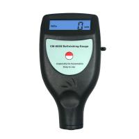
5.5 Magnetic method
5.5.1 General
For most dry film thickness magnetic Testers, a reading is required before it can be taken. Calibrate the instrument within the expected coating thickness range according to the manufacturer's instructions.
5.5.2 Principles
The thickness of the paint film is determined based on the interaction of the magnetic field with the substrate. Depending on the force required to remove the magnet from the coating (see Method 7A in 5.5.5) or the change in the magnetic field of the magnet (see 5.5.6, 5.5.7 and 5.5. 8 methods 7B, 7C and 7D) to determine the thickness of the paint film.
5.5.3 Scope of Use
The magnetic method is suitable for coatings on metal substrates.
For methods 7A, 7B, and 7C, the substrate needs to be ferromagnetic; For Method 7D, the substrate is non-ferromagnetic.
The properties of the coating make the instrument valid for readings when it comes into contact with the coated surface.
5.5.4 General
The magnetic field generated by the instrument is affected by the following factors:
1. The geometry of the substrate (size, curvature and thickness;
- the properties of the substrate (e.g. magnetic permeability, electrical conductivity and properties resulting from any pre-treatment;
- the roughness of the substrate;
- Other magnetic fields (residual magnetism of the substrate and external magnetic fields).
5.5.5 Method 7A – Magnetic Suction Disengagement Tester
5.5.5.1 Instruments
The instrument contains a magnet and the thickness of the paint film is determined based on the attraction between the magnet and the substrate (see Figs. 13a) and 13b).
Note: The instrument shown in Figure 13a) can be used in any orientation. Figure 13b) is designed to be used in only one direction due to gravity.
5.5.5.2 Steps
Place the instrument's magnet against the coating to lift the magnet away from the coating by placing the instrument next to the coating. The film thickness can be determined from the force required to remove the magnet from the specimen.
5.5.6 Method 7B – Magnetic flux Tester
5.5.6.1 Instruments
The instrument contains a magnet that measures the thickness of the paint film based on the change in the magnetic field of the magnet due to the influence of the substrate, and the magnetic field is measured with a Hall probe (see Figure 14).
5.5.6.2 Steps
Place the instrument on the coating in a direction perpendicular to the surface of the coating and read the thickness value directly from the dial or calculate it according to the manufacturer's instructions.
5.5.7 Method 7C – Induced Magnetic Tester
5.5.7.1 Instruments
The instrument contains an electromagnet, and the thickness of the paint film is determined based on the change in the magnetic field as the electromagnet approaches the ferromagnetic substrate (see Figure 15). Electromagnets generate low-frequency (LF, e.g., 60Hz~400 Hz) alternating electromagnetic fields (see ISO 2718).
5.5.7.2 Steps
The instrument is placed on the coating in a direction perpendicular to the surface of the coating, and the film thickness is calculated based on the change in magnetic flux.
5.5.8 Method 7D – Eddy Current Tester
5.5.8.1 Instruments
The instrument contains an electromagnet and determines the thickness of the paint film based on the change in the magnetic field caused by the eddy currents generated by the conductive substrate (see Figure 16). Electromagnets generate high-frequency (HF, e.g., 0.1 MHz ~ 30 MHz) alternating electromagnetic fields (see ISO 2360).
5.5.8.2 Steps
Place the instrument on the coating in a position perpendicular to the surface of the coating.
5.6 Radiation Method
5.6.1 Principle
Using a radioactive isotope as a radiation source, the thickness of the paint film is determined based on the interaction between ionizing radiation and the coating.
5.6.2 Scope of Application
The radiation principle applies to any film-substrate combination, as long as the atomic number of the paint and substrate differs by at least 5 (see ISO 3543).
5.6.3 General
The measurement of paint film thickness is influenced by the following factors:
1. The geometry of the substrate (size, curvature);
impurities on the surface of the coating one by one;
- Changes in coating density.
5.6.4 Method 8 – β radiology
5.6.4.1 Instruments
β antiscatterer (see Figure 17) consists of the following components:
1. The radiation source (radioisotope) mainly emits β particles whose energy is suitable for the thickness of the paint film to be measured;
- the probe or measuring system has a series of pores and contains β Detector that counts the number of backscattered β particles (e.g., a Geiger counter);
One by one data processing and display system.
5.6.4.2 Check
If necessary, calibrate and adjust the instrument with a reference material, which should have the same coating and substrate composition as the specimen to be tested as far as possible.
5.6.4.3 Steps
Operate the instrument according to the manufacturer's instructions
5.7 Photothermal method
5.7.1 Principles
The paint film thickness is determined by measuring the time difference between the heat wave radiating to the coating and the returning wave, which can be a heat wave or an ultrasonic wave (see Figure 18).
Regardless of the excitation or detection method, all photothermal methods have the same principle: periodic or pulsed energy is applied to the specimen in the form of heat, and then the local temperature increase is detected.
The paint film thickness is obtained by comparing the time difference measured on the specimen with the value measured on a film of known thickness under fixed conditions (excitation energy, pulse length, excitation frequency, etc.) with the same instrument (see 5.7.4.2).
5.7.2 Scope of Application
The photothermal principle is applicable to almost all film-substrate combinations. This method can also be used to determine the thickness of individual coatings as long as the coatings in a multi-coat system are well distinguished from each other in terms of thermal conductivity and reflectivity.
The minimum substrate thickness required varies depending on the measuring system used (see 5.7.4.1.1) and the varnish-substrate combination.
5.7.3 General
Test methods are classified as destructive and non-destructive, and their classification depends on the purpose of the coating. The absorption of heat energy by the coating may have an effect on the coating due to the local thermal effects generated.
5.7.4 Method 9 – Determination of thermal properties
5.7.4.1 Instruments and reference standards
5.7.4.1.2 Measurement systems
There are a number of methods to generate thermal waves on the coating material and the thermal effects of the heated part of the test specimen (see EN 15042-2). Thermal radiation sources (e.g., laser sources, light-emitting diodes, incandescent light sources) are primarily used as excitation systems for coatings.
The following assays are available:
- detection of the returned thermal radiation (photothermal radiation measurement);
- Detection of changes in the refractive index (measured in hot air above the measurement area)
- Thermoelectric detection (measurement of heat flow).
5.7.4.1.2 Reference standards
Calibration requires reference standards with different absorption properties and different film thickness ranges (see EN 15042-2).
5.7.4.2 Check
For each film-substrate combination (especially for each coating), if required, the measuring system is calibrated and adjusted with a reference standard (see 5.7.4.1.2).
5.7.3 Steps
Operate the instrument according to the manufacturer's instructions, read the thickness value directly from the display or calculate it according to the manufacturer's instructions.
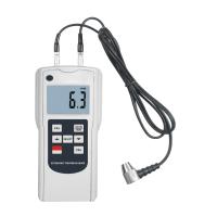
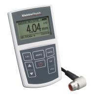
5.8 Sonic method
5.8.1 Principle
In the acoustic method, the paint film thickness is determined based on the propagation time of the ultrasonic pulse through the coating.
5.8.2 Scope of application
The acoustic principle applies to all varnish-substrate combinations.
The velocity of sound is the same in the same coating and is significantly different from that in adjacent coatings or substrates.
Note: The non-uniformity of the coating (if aluminum powder is present) and the non-uniformity of the substrate (such as the wood grain of the wood) may affect the results.
5.8.3 General
The sound field is influenced by the geometry (size, curvature, and roughness) of the substrate.
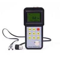
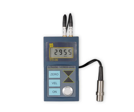
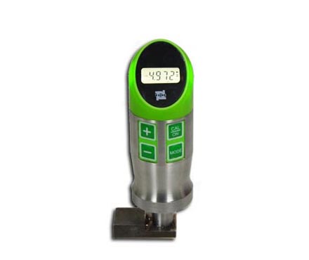
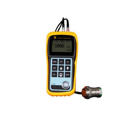
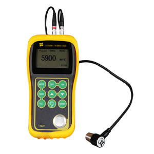
5.8.4 Method 10 – Ultrasonic Thickness Gauge
5.8.4.1 Instruments
The instrument has an ultrasonic transmitter and receiver to determine the thickness of the paint film based on the time of sound propagation (see Figure 19).
5.8.4.2 Steps
The couplant is applied to the coating to which the thickness needs to be determined. Place the instrument probe face flat on the coating. Operate the instrument and assay results according to the manufacturer's instructions.
6 Determination of the thickness of the uncured powder coating
6.1 General
Appendix A provides an overview of the method for determining the thickness of uncured powder coatings.
6.2 Gravimetric analysis
6.2.1 Principles
The thickness tp of the uncured powder coating, measured in micrometers (μm), is calculated from the difference in quality between the unpainted specimen and the painted specimen as follows in equation (4) below:
where:
m0 - the mass of the unpainted specimen, in grams (g);
m - the mass of the painted specimen, in grams (g);
A - the surface area of the coating, in square meters (㎡);
PP – the density of the applied uncured powder coating in grams per milliliter (g/ml).
Note: The density of powder coatings can be determined according to ISO 8130-3.
6.2.2 Scope of Application
Gravimetric analysis is versatile.
6.2.3 General
Gravimetric analysis was used to obtain the average thickness of the paint film over the entire coating surface area. When applying powder, the back side of the specimen should be covered to avoid measurement errors due to topical application (jet escape) on the back side.
6.2.4 Method 11 – Mass Difference Method
6.2.4.1 Instruments
The maximum weighing range of the balance is required to be 500g and the accuracy is 1mg.
6.2.4.2 Steps
The quality of the clean unpainted specimen is weighed first, the paint is applied, and then the quality of the painted specimen is weighed, and the paint film thickness is calculated according to Eq. (4). The second weighing should be performed immediately after powder application.
6.3 Magnetic method
6.3.1 Principle
The thickness of the paint film is determined based on the interaction between the magnetic field and the metal substrate. According to the change of the magnetic field, the thickness of the paint film is obtained.
6.3.2 Scope of application
The magnetic method is suitable for painted metal substrates.
For Method 12A, the substrate needs to be ferromagnetic; For Method 12B, the substrate needs to be non-ferromagnetic.
6.3.3 General
The magnetic field generated by the instrument is affected by the following factors:
- the geometry (size and thickness) of the substrate;
- the properties of the substrate (e.g. magnetic permeability, electrical conductivity and properties resulting from any pre-treatment);
- the roughness of the substrate;
- Other magnetic fields (residual magnetism of the substrate and external magnetic fields).
Measurements are only allowed on flat surfaces.
6.3.4 Method 12A – Induced Magnetic Tester
6.3.4.1 Instruments
The instrument contains an electromagnet, and the thickness of the paint film is determined by the change in the magnetic field as the electromagnet approaches the ferromagnetic substrate (see Figure 20). Electromagnets generate low-frequency (LF, e.g. 60Hz~400Hz) alternating electromagnetic fields (see ISO 2178).
Probes should be positioned in such a way that the impact of the probe on the thickness of the uncured powder coating should be minimized.
6.3.4.2 Steps
Place the instrument on the coating in a direction perpendicular to the surface of the coating and read the thickness value directly from the display or calculate it according to the manufacturer's instructions.
6.3.5 Method 12B – Eddy Current Tester
6.3.5.1 Instruments
The instrument contains an electromagnet and determines the thickness of the paint film based on the change in the magnetic field caused by the eddy currents generated by the conductive substrate (see Figure 16). Electromagnets generate high-frequency (HF, e.g. 0.1 MHz to 300.1 MHz) alternating electromagnetic fields (see ISO 2360).
Probes should be positioned in such a way that the impact of the probe on the thickness of the uncured powder coating should be minimized.
6.3.5.2 Steps
Place the instrument on the coating in a direction perpendicular to the surface of the coating and read the thickness value directly from the display or calculate it according to the manufacturer's instructions.
6.4 Photothermal method
6.4.1 Principle
The paint film thickness is determined by measuring the time difference between the heat wave radiating to the coating and the returning wave, which can be either thermal or ultrasonic, (see Figure 18).
Regardless of the excitation or detection method, all photothermal methods have the same principle: periodic or pulsed energy is applied to the specimen in the form of heat, and then the local temperature increase is detected.
The paint film thickness is obtained by comparing the time difference measured on the specimen with the value measured with the same instrument under fixed conditions (excitation energy, pulse length, excitation frequency, etc.) for a film of known thickness (see 6.4.4.2).
6.4.2 Scope of application
The photothermal principle is applicable to almost all film-substrate combinations. This method can also be used to determine the thickness of individual coatings as long as they are well distinguished from each other in terms of thermal conductivity and reflectivity in a multi-coat system.
The minimum substrate thickness required varies depending on the measuring system used (see 6.4.4.1.1) and the varnish-substrate combination.
6.4.3 General
Test methods are classified as destructive and non-destructive, and their classification depends on the purpose of the coating. The absorption of heat energy by the coating may have an effect on the coating due to the local thermal effects generated.
6.4.4 Method 13 – Determination of thermal properties
6.4.4.1 Instruments and reference standards
6.4.4.1.1 Measurement systems
There are a number of methods to generate thermal ripples on the coating material and thermal effects on the heated parts of the test specimen (see EN 15042-2). Thermal radiation sources (e.g., laser sources, light-emitting diodes, incandescent light sources) are primarily used as excitation systems for coatings.
The following assays are available:
Detect the returned thermal radiation one by one (photothermal radiation measurement);
Detect changes in the refractive index one by one (measured in hot air above the measuring area);
11. Thermoelectric detection (measurement of heat flow)
6.4.4.1.2 Reference standards
Calibration requires reference standards with different absorption properties and different film thickness ranges (see 15042~2 "18").
6.4.4.2 Check
For each film-substrate combination, especially for each film material, the measurement system can be calibrated and adjusted with a reference standard (see 6.4.4.1.2) if required.
6.4.4.3 Steps
Operate the instrument according to the manufacturer's instructions, read the thickness value directly from the display or calculate the thickness according to the manufacturer's instructions.
7 Measurement of paint film thickness on rough surfaces
7.1 General
The roughness of the substrate surface affects the film thickness measurement results. Therefore, special consideration is required for the steel substrate to be sprayed and cleaned. If the paint is applied to a jet-cleaned steel substrate, the measurement of the paint film thickness is more complex than that on a smooth surface. The results are affected by the properties of the substrate and may vary from point to point; It is also influenced by the design of the measuring equipment. In fact, when measuring the thickness of the paint film on the steel substrate for jetting, the setting procedure of the instrument is different, which can lead to a significant difference in the dry film thickness reading.
In addition to the different results of using a certain type of instrument to measure on the surface of the jet cleaning, there are also many problems with instrument zeroing, such as:
- Poor repeatability;
The thickness values measured by placing the flakes one by one on such a surface are variable (the thicker the flakes, the greater the apparent increase in the thickness of the flakes)
One by one, when the surface roughness of the steel substrate is unknown, it brings uncertainty.
The purpose of the method described in this chapter is to minimize variability in results and maintain operational consistency when determining the thickness of the paint film on the jet-cleaned steel substrate. When determining the thickness of the paint film on a rough surface with an induced magnetic Tester, this method requires that the instrument need to be zeroed on a smooth steel surface in advance.
This method measures the paint film thickness from a virtual plane between the peaks and valleys on the surface of a rough substrate, which is typically 25 μm below the peak (i.e., about half of the surface roughness of the jet cleaning surface (the surface roughness of the jet cleaning surface is expressed as the height from the bottom to the peak)), with the exception of surfaces with a surface profile grade of "fine" specified in ISO 8503-1.
This method describes a representative parameter determination of the thickness of the dry coating on the jet-cleaned steel substrate. In order for the results to be meaningful, the actual film thickness measured by the standard method should not be less than 25 μm, and preferably greater than 50 μm.
Other methods for determining the thickness of coatings on rough surfaces are described in ISO 19840.
7.2 Instruments and Materials
7.2.1 Paint film thickness Testers, of the inductive type, are used in Method 7C (see 5.5.7).
Note: Equipment equipped with tools to calculate the mean standard deviation of measured values and other statistical parameters should be used with caution and it is recommended that it should be used by personnel trained in statistical techniques.
7.2.2 The calibration sheet is foil-type, with a defined thickness value (traceable to nationally recognized standards) and a thickness close to the expected film thickness.
Note: Unqualified lamellae are allowed as long as they are calibrated on site.
7.2.3 Smooth steel plate, free of iron scales and rust, similar to magnetic and painted steel plate, with a thickness of at least 1.2mm, for on-site calibration of instruments.
7.3 Steps
7.3.1 Check
If needed, calibrate and adjust the instrument according to the manufacturer's instructions prior to use. The steel plate is calibrated with a smooth steel plate, and the smooth steel plate is polished with 400 sandpaper before use to remove all rust. The calibration lamellae is placed between the smooth steel plates of the probe and calibrated with lamellae thicknesses that are higher and lower than the expected varnish thickness.
7.3.2 Measurements
Measure the dry coating thickness on a rough surface using the same method used to measure the dry coating on a smooth steel plate according to the instrument manufacturer's instructions. See 7.3.3 for the number of readings.
7.3.3 Number of readings
For each test area, it is recommended to take at least three readings that are evenly spaced.
Guiding suggestion: For flat plates, take at least two test areas per square meter; For the beam belly, take four test areas per meter length; For the flange, take two test areas per meter length; For pipes, take two or more test areas per meter of length (depending on the pipe diameter).
For offshore or other offshore workpieces, it is usually advisable to take more readings.
8 Test report
The test report should contain the following information:
a) all necessary information (manufacturer, product name, batch number, etc.) to identify the product to be tested;
b) indicate the number of this standard (GB/T 13452.2);
c) the methods and instruments used;
d) the results of the test, including the results of each measurement and its average;
e) any deviations from the prescribed test procedures;
f) any anomalies found during the test;
g) Date of the trial.
If required, the test report can also contain the following information:
h) details of the substrate (material, thickness and pretreatment);
i) the method used to apply the substrate, whether it is a single coating or a multi-coating system;
j) the time and conditions under which the coating is dried/cured (including baking) and, if required, any aging prior to thickness measurement also recorded in the report;
k) the relevant surface area, the test area and the number of measurements taken in each test area;
l) The minimum and maximum values of the average paint film thickness and its standard deviation, the local paint film thickness and its standard deviation, and the local paint film thickness.


- 1Principle, Characteristics and Application of Wet Film Comb
- 2Determination method of dry and wet paint film thickness
- 3How to detect the thickness of steel structure paint?
- 4Measuring method of ISO 2808 film thickness
- 5What are the main differences between Varnish and Paints?
- 6Coating Thickness Gauge measurement circuit board film thickness scheme
- 7Epoxy asphalt film thickness measurement solution
- 8Coating film thickness measurement scheme
- 9Application of coating Thickness Gauge in thickness measurement of steel pipe paint film