Introduction to the calibration method of thermocouple
1. Calibration of thermocouples
During long-term use, the hot end of the thermocouple will be subject to corrosion, oxidation, and material rebonding, resulting in changes in thermoelectric characteristics, which will increase the measurement error. For the accuracy of the measurement results, the thermocouple needs to be calibrated regularly. Experiment to measure the change of thermoelectric potential. When the change exceeds the specified error range, you can replace the thermocouple wire or cut off a section of the hot end of the original thermocouple, and use it after re-welding. It also needs to be verified before use.
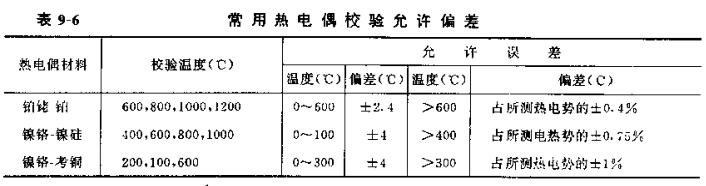
During thermocouple calibration, generally check whether the thermoelectric potential is within the allowable deviation range according to the temperature values of each point listed in Table 9-6. The temperature points listed in the table need to be controlled within the range of ±10°C. If EU and EA thermocouples are used below 300°C, a calibration point of 100°C should be added, and a standard mercury thermometer should be used for comparison during calibration. When the temperature point to be calibrated is between 300 and 1300°C, use a standard platinum boat-platinum thermocouple.
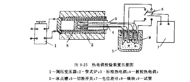
The calibration device of thermocouple is composed of tube furnace, freezing point heater, voltage regulating transformer, DC potentiometer, switch and standard thermocouple, etc. The calibration system is shown in Figure 9-25. The inner diameter of the tube furnace commonly used to check the thermocouple is 50~100mm, the length of the tube is 600~1000mm, the maximum current is 10A, and the maximum temperature is 1300°C. The temperature value is achieved by adjusting the current through the pressure transformer.
When calibrating thermocouples, pay attention to the following points:
(1) When calibrating the thermocouple of Platinum Ship 1, pull out the thermocouple to be calibrated from the protective tube, tie the thermocouple to be calibrated with the working end of the standard thermocouple with platinum wire, and insert it into the tube furnace A place with an even temperature. When calibrating nickel-chromium-nickel-silicon and nickel-chromium-copper thermocouples, in order to avoid harmful effects of the calibrated thermocouple on the standard thermocouple, put the t-marked thermocouple on a quartz sleeve, and then place the calibrated thermocouple The working ends of the couple and the standard thermocouple protection tube are tied together and inserted into the uniform temperature field in the tube furnace. Sometimes in order to ensure that the hot end of the thermocouple to be calibrated and the standard thermocouple are at the same temperature, the hot end of the commercial thermocouple can be placed in a metal block (nickel block is better), and the operating block is placed in the center of the P in a uniform temperature field.
(2) After the thermocouple is put into the furnace, the furnace mouth is blocked tightly with asbestos that has been well sintered, and the cold end of the thermocouple is placed in the freezing point tank to maintain 0 °C.
(3) The temperature of the thermocouple inserted into the furnace is generally 300mm; the insertion depth of the shorter thermocouple can be appropriately reduced, but not less than 150mm.
(4) Adjust the voltage regulating transformer during calibration. When the furnace temperature reaches the required calibration temperature within 10°C and the furnace temperature does not change by more than 0.2°C per minute, you can use the potentiometer to read each The corresponding thermoelectric potential value at temperature.
(5) For each temperature: the readings of the calibration point shall not be less than 4 times, and then take the arithmetic mean value, calculate the error of each thermocouple at each temperature point, and see if it exceeds the specified value in Table 9-6 Allowable error value.