Coating Thickness Gauge Measurement principle analysis of variable magnetoresistance method
Generally, the variable reluctance sensor is aimed at measuring the non-magnetic coating on the magnetic metal substrate. Its structure diagram is shown in the figure. When the air gap is small, the magnetic field in the air gap can be considered to be uniform. If the magnetic circuit loss is ignored, the total reluctance of the magnetic circuit is

Usually, the reluctance of the air gap C (μr=1) is much larger than that of the iron core and armature (μr=~5000, the above formula can be approximated as

Thus, the inductance in the coil is:


Structural diagram of variable reluctance sensor and its output characteristic curve
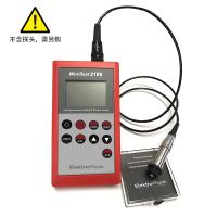
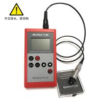
When the coil turns W and the air gap cross-sectional area S0 are constant, the inductance L is only a function of the air gap. The above formula reflects the theoretical basis for the application of variable gap inductance sensors. Among them, the coil and iron core constitute the measuring head of the Thickness Gauge.
When measuring, the thickness of the non-magnetic coating on the magnetic metal substrate is different, so that the relative distance between the iron core in the measuring head and the magnetic metal substrate is different, causing the reluctance change in the magnetic circuit, resulting in the change of the inductance in the coil .
As shown in the figure, its output characteristics are nonlinear, and the sensitivity decreases with the increase of the air gap. Therefore, the general gap b is 0.2-1mm. In order to reduce nonlinearity, the measuring range needs to be limited to a small range, generally less than 1/5 of the gap. In addition, it is difficult to manufacture and assemble such sensors. Because the measurement range of the variable gap inductive sensor is inconsistent with the sensitivity and linearity, the variable gap inductive sensor is suitable for the occasion of measuring small displacement. The measuring range of the currently commercially available coating Thickness Gauges using the magnetic induction method is generally 0.5-1250 μm. Obviously, this cannot meet the measuring range (0.1mm - 3mm ) required in this subject.
To sum up, there is currently no satisfactory solution to the problem of non-destructive thickness measurement of wave-absorbing coatings, and there is no ready-made non-destructive thickness measurement product available. How to design and manufacture a system that can be applied to the thickness measurement of absorbing coatings based on the existing coating non-destructive testing technology has become a key technology in the research of absorbing materials and an important topic in the application research of absorbing materials. .


- 1Nondestructive measurement Coating thickness
- 2Principle, application and selection of traffic coatings Coating Thickness Gauge
- 3Principle, Application and Selection of Eddy current Coating Thickness Gauge
- 4Principle, Application and Type Selection of Electronic Coating Thickness Gauge
- 5Explore the principle, application and selection of phosphating layer Coating Thickness Gauge
- 6Principle, Application and Type Selection Analysis of Chrome Coating Thickness Gauge
- 7Principle, Application and Selection of Coating Thickness Gauge for inner wall of small pipe
- 8Basic principle and application scenario of steel Coating Thickness Gauge
- 9Principle and Application Analysis of Coating Thickness Gauge