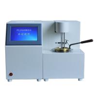
Air Compressor use and maintenance instructions
工作原理及主要功能件介绍:
概述:LU90-180系列螺杆式空气压缩机是喷油单级螺杆压缩机,采用联轴器直连传动,带动主机转动进行
空气压缩,通过喷油对主机内的压缩空气进行冷却,主机排出的空气+油混合气体经过粗、精两道分离,将压缩空气中的油分离出来,压缩空气中的水分在气水分离器中被分离出来,最后得到洁净的压缩空气。冷却器用于冷却压缩空气和油。
工作原理:
螺杆压缩机是容积式压缩机中的一种,空气的压缩是靠装置于机壳内互相平行啮合的阴阳转子的
齿槽之容积变化而达到。转子副在与它精官配合的机壳内转动使转子齿槽之间的气体不断地产生周期性的容积变化而沿着转子轴线,由吸入侧推向排出侧,完成吸入、压缩、排气三个工作过程。
空气流程:
空气→空气过滤器1→减荷阀2→主机3→油气分离器4、5→最小压力阀6→冷却器7→气水分离器16→出口(供气)。
气水分离器17分离出来的冷凝水经过排污电磁阀放掉。
润滑油流程:
润滑油→分离油罐4→温控阀9→冷却器7(或旁路)→油过滤器10→主机3。
空气+油混合气体在分离油罐内经过改变方向、旋转,大部分的油被分离出来,剩余的小部分油再经过油精分离器5被分离出来,这部分油被插入油精分离器内的管子抽出,经节流单向阀流入主机的低压部分,节流单向阀的节流作用是使被分离出来的油全部被及时抽走,而又不放走太多的压缩空气,如果节流孔被堵,油精分离器内将积满油,会严重影响分离效果;节流单向阀的另一个作用是防止停机时,主机内的润滑油倒流入油精分离器内。
分离油罐内的热油流入温控阀,温控阀According to流入油的温度控制流到冷却器和旁通油量的比例,以控制排气温度不至于过低,过低的排气温度会使空气中的水分在分离油罐内析出,并使油乳化而不能继续使用,最后油经过油过滤器后喷入主机。
润滑油循环由分离油罐与主机低压腔之间的压差维持,为了在机器运行过程中保持油的循环,需要保证分离油罐内始终有0.2~0.3MPa的压力,最小压力阀6就是起到这一作用的。
空气过滤器:
空气过滤器主要由纸质滤芯与壳体组成。空气经过纸质滤芯的微孔,使灰尘等固体杂质过滤在
滤芯的外表面,不进入压缩机主机内,以防止相对运行件的磨损和润滑油加速氧化。因此,应According to使用环境和使用时间,及时予以清洁或更换纸质滤芯。其清洁方法为将滤芯取出轻轻敲其上下端面,即可清洗滤芯上的灰尘污物。切忌用油或水刷洗。如发现滤纸破损或尘污多堵塞严重而清除不净时,则须更换新件。
减荷阀:
减荷阀主要由阀体、阀门、活塞、气缸、弹簧、密封圈等组成,其端面设有集成控制块,上面有放
气阀及控制电磁阀,集成了通断调节和停机放空等功能。当压缩机起动时,减荷阀阀门处于关闭位置,以减少压缩机的起动负荷;当压力超过额定排气压力时,微电脑控制器发出信号使用电磁阀失电,减荷阀阀门关闭,使压缩机处于空载状态,直到压力降低到规定值时,阀门打开,压缩机又进入正常运转,此过程谓通断调节。减荷时有小部分的气体通过阀内的小孔放掉,以平衡减荷阀小孔的吸入气量,使分离油罐内的压力保持在0.2~0.3MPa,维持正常的润滑油循环;减荷阀的开启关闭动作是由调节系统的电子控制器和装在减荷阀端面的电磁阀自动控制的,减荷阀的开启关闭动作是否灵活,对压缩机的可靠性是很重要的,因此,减荷阀应定期保养,以维持良好的工作状态,保养时,须将零件拆下,检查各磨擦表面的磨损情况,特别需注意检查橡胶密封圈表面,如有损坏或裂缝,则须更换新件,在重新安装时,各零件应清洗干净,金属零件的磨擦表面应涂上润滑油。
油气分离器:
油分离部分主要由分离油罐4和油精分离器5组成,来自主机排气口的油气混合物进入分离油
In the tank space, after changing the direction and turning, most of the oil gathers in the lower part of the tank, and the compressed air containing a small amount of lubricating oil passes through the oil separator 5 to make the lubricating oil fully collected, and the oil collected by the oil separator The lubricating oil is drawn out by the pipe inserted into the oil separator, and flows into the low-pressure part of the main engine through the throttling check valve 8. A safety valve is installed on the upper part of the oil separation tank. When the pressure in the container is too high, the air will be released through the safety valve to ensure the safe use of the compressor. The surface needs to remain in the middle of the oil level indicator. The differential pressure transmitter 19 is used to detect the blockage of the oil separator. When the oil separator is seriously blocked, the differential pressure transmitter will act, and the indicator light of the oil separator will be on, so it should be replaced in time. After the compressor stops working for a period of time, the moisture in the air will condense and deposit on the bottom of the separation oil tank, so the water should be drained through the oil drain valve 15 installed at the bottom of the separation oil tank to prolong the service life of the lubricating oil. During use, if there is a large amount of oil in the exhaust, check whether the oil suction pipe and the throttle check valve 8 are unblocked. If it is confirmed that there is no problem, remove the oil separator and check it. If it is damaged, it will cause a filter short circuit or serious blockage, and it needs to be replaced with a new one.
Minimum pressure valve:
The minimum pressure valve is composed of a valve body, a valve core, a spring, a sealing ring, an adjusting screw, etc., and is installed at the outlet of the oil separator.
The purpose is to keep the pressure in the oil separation tank from falling below 0.3MPa, so that the oil-containing compressed air can be better separated in the separator and reduce the loss of lubricating oil. At the same time, it can ensure the gas pressure required to establish the oil pressure. The minimum pressure valve also acts as a one-way valve to prevent backflow of compressed air in the system during shutdown. The holding pressure of the minimum pressure valve has been adjusted at the factory. If the holding pressure changes due to long use time, it can be adjusted through the adjusting screw on the valve.
Cooler:
The function of the cooler is to cool the compressed air and lubricating oil discharged from the compressor. The plate-fin cooler is used in the air-cooled unit, all of which are made of
The water-cooled unit made of aluminum alloy material is welded and used in an effective copper shell and tube cooler. Most of the heat generated by the compressor is taken away by the lubricating oil, and the oil is cooled by the cooling air (for water-cooled type) by forced convection. for water) away. In the air-cooled heat exchange process, the thermal resistance of the air side plays a leading role, so the surface of the heat sink and plate tube should be kept clean. If there is a lot of oil and dirt (scale for water-cooled units), it should be cleaned regularly.
Gas water separator:
After the moisture in the compressed air is separated by the gas-water separator, it is drained regularly by the sewage discharge solenoid valve installed at the bottom of the gas-water separator. when
When it is necessary to repair the sewage solenoid valve, the maintenance ball valve should be closed, and the manual sewage ball valve should be opened moderately to ensure that too much compressed air is not wasted. At this time, the sewage solenoid valve can be removed for maintenance.
Temperature control valve:
The temperature control valve controls the minimum oil injection temperature for compression, because lower oil injection will make the exhaust temperature of the compressor lower, and precipitate in the separation oil tank
Condensed water will deteriorate the quality of lubricating oil and shorten its service life. When the oil injection temperature is controlled to be higher than a certain temperature, the mixture of exhausted air and lubricating oil will always be higher than the dew point temperature.
Its working principle is that the oil from the separation oil tank enters the E port of the temperature control valve. When the temperature is lower than 70°C, all the oil bypasses and enters the H port, and then enters the main engine after being filtered; when the temperature is greater than 70°C, the temperature control element 5 Stretch, push the piston 2, start to close the channel between E-H, and gradually open the channel between E-U, the ratio of the flow area of the two channels is determined by the oil inlet temperature, and the oil flowing out of U is cooled Then it enters the R port, mixes with the hot oil passing through the H bypass, and enters the main engine after being filtered. When the oil inlet temperature is high, the channels between E-H are all closed, and all the oil enters the cooler to be cooled.
Oil filter: The function of the oil filter is to filter out the particles, dust and other impurities in the lubricating oil circulation process to ensure the normal operation of the compressor
For operation, a pressure difference transmitter is installed on its upper part. If the pressure difference transmitter gives an alarm indication when the oil filter is blocked, the oil filter should be replaced. Parameter setting and modification:
Parameter modification without password input: Use the ▲▼ keys to find the page where the parameter is to be set. At this time, there is a four-force shape at the modifiable parameter, and then
Then use the ↓↑ key to move the quadrilateral to the parameter to be modified, and press the ENTER key to confirm. At this time, the cursor will flash at the original parameter. Use the ↓↑ key to input the required parameters, and use the → key to move the cursor. After the parameter setting is completed, press the ENTER key to confirm the setting.
On-machine control and remote control settings:
Input 1111 after setting to machine side control, the compressor is set to machine side control state. Enter 2222 after setting to remote control, the compressor is set to remote control status.
On and off setting of high pressure delay shutdown function:
When the high pressure delay stop function is enabled, when the discharge pressure of the compressor reaches the upper limit, if the discharge pressure of the compressor has not dropped below the lower limit within the set time, the compressor will automatically stop; When the air pressure drops to the lower limit, the compressor starts automatically.
Enter 1111 after the display 1111 is open, and the high pressure delay shutdown function is opened.
Enter 2222 after the display 2222 is off, and the high pressure delay shutdown function is turned off.
压缩机气量控制、安全装置和电气原理:控制系统的工作原理:
控制系统能According to压缩空气的消耗量来自动控制压缩机的排气量,保持压缩机在预定的最高和最低排气压力范围下工作,控制系统是靠压缩空气的压力变化来达到自动控制。该系统主要由压力传感器、电磁阀、减荷阀等组成。
压缩机一经起动,压缩机是处于空载运转(减荷阀处于关闭状态),当油压升到压力约0.2MPa,且运行时间达到1~3分钟,按下加载/减荷按钮,压缩机开始吸气工作(减荷阀处于全开状态),分离油罐内的压力逐渐升高,当工作压力大于最小压力阀设定的开启压力时,压缩机排出压缩空气,压缩机处于全负荷运行状态。
当用气量小于额定排气量时,系统压力升高,当压缩机工作压力达到系统调定的上限值,PLCL输出信号,减荷阀上的电磁阀断电,减荷阀吸气口关闭,压缩机卸载运转,如压力下降到系统调定的下限值时(上限值与下限值之差可调,一般为0.05~0.15MPa),减荷阀上的电磁阀得电,减荷阀吸气口开启,压缩机全负荷运行。
安全阀:
装在分离油罐上,当调节系统万一发生故障,排气压力上升达到安全阀开启压力时,气体项开阀芯
向大气喷射,使分离油罐的压力下降,当压力下降到安全阀关闭压力时,安全阀自动关闭。一般,安全阀开启压力比压缩机的额定排气压力高0.1~0.2MPa。
起压保护:
当压缩机的实际排气压力高出设定的额定排气压力0.07MPa时,微电脑控制器自动切断电动机电源,使压缩机停机,控制器屏幕显示压力超高故障信息。
高温保护:
当压缩机排气温度超过调定值(150℃)时,由接在主机排气孔口处的温度传感器将信号传到微
电脑控制器,自动切断电动机电源,使压缩机紧急停机。
冷却水流量低保护:当流量过低时,水流量开关动作,如果在20秒钟内,水流量还不恢复正常,且排温达
到110℃时,则自动切断电动机电源,使压缩机停机。
油过滤(精油分离)器堵塞报警:当油过滤(油精分离)器堵塞,压差达到0.1~0.15MPa时,压差发讯器动作,控制器屏幕显示故障信息,压缩机不停机。
进气过滤器堵塞报警:当进气过滤器堵塞,压差发讯器动作,控制器屏幕显示故障信息,压缩机不停机。
对水冷机组,冷却水供水压力应为0.2~0.6MPa。
开机前的准备工作:
1.检查各零部件的联接是否有松动,如有松动,需要拧紧,以免工作中有漏油、漏气或其它事故发生。2.检查各测量仪表时否有松动或损坏。
3.按电气原理图接好电器及地线。对控制柜内的接线进行检查,避免由于运输原因造成的接线松动引起的故障。
4.检查压缩机的润滑油是否足够,若不够时,应予加足。停机(或出厂时间)超过四个月以上未使用的机
组,需往主机的加油口处加入3升左右的润滑油,防止起动时主机内无油。加入主机的油应保证绝对清洁、无杂质。
5.收拾机组附近及放在机组上的一切无关物件。
压缩机的启动:
1.合上机组供电电源开关(用户自备,并按机器总功率选铜芯软线接入电控柜),打开冷却水阀(水冷机组)。
2.将机组空气排出阀打开。
3.新安装的压缩机应检查旋转方向,方法是点动压缩机电机(时间应尽可能短),仔细观察电动机旋转方
向是否符合规定的转向,如果转向不对请调换三相电源线的其中两条接线的位置。点动压缩机方法如下:
按下启动按钮,压缩机刚开始转动时,立刻按急停按钮停机,同时观察压缩机的旋转方向是否正确。4.转向正确后,再启动压缩机使电动机达到额定转速,如有不正常响声,需要消除。
5.使压缩机进行正常运行,油罐内压力应很快升到0.2MPa,并保持在这一压力,排气温度应不大于100℃。在这一工况下运转1~3分钟,按下加载/减荷键,压缩机进入正常工作。
压缩机运转中注意事项:
1.压缩机运转工作后,应经常注意油面高度,如出现油位下降快,排出的压缩空气含油量大。
2.注意各仪表的指示读数是否在正常的范围内,气压应在额定压力范围内。在压缩机吸气温度≤40℃时,排气温度应≤100℃。
3.当精油分离器及油过滤器进出口压差过大,控制器屏幕显示报警,压缩机仍可运转,但应及时更换新件,以免引起机器缺油造成烧机严重事故。
4.当排气温度过高,控制器屏幕显示报警时,主机自动停机,请查明原因并处理故障后,方可重新起动。
压缩机的停机:需要停机时,关闭出口阀,按下停机键,机组按设定程序停机,停机后减荷阀内的放气孔和油分离顺上的放气电磁阀应立即放气,待放气完毕后拉下供电电源开关。关冷却阀(水冷机组)。
急停按钮只在紧急情况下使用。
注意事项:
1.如果停机时不关闭出口阀,油罐内的压力可能因跑气过快而突降,油中的空气吐出,产生大量的油泡沫
浸泡油精分离器,导致分油效果不良。
2.停机后,一般需要等2~5分钟才拉下供电源开关,保证油罐内的压缩空气通过放气电磁阀放完后,以便下次启动无负荷。
3.冬天,停机后应关闭冷却水阀(水冷机组),并排于油冷却器中的冷却水,以免结冰胀坏冷却器。
压缩机的日常维护:
排放冷凝水:空气中的水分可能会在油罐中凝结,特别是在潮湿天气,当排气温度低于空气的压力露点或停机冷却时,会有更多的冷凝水析出。油中含有过多的水份将会造成润滑油的乳化,影响机器的安全运行,如:——造成压缩机主机润滑不良;
——油分离效果变差,油精分离器压差变大;
——引起机件锈蚀。
因此,应According to湿度情况制定冷凝水排放时间表。
冷凝水的排放方法:
应在机器停机,待机器得到充分冷却,冷凝水得到充分沉淀后进行,如旱上开机前。1.拧出球阀前螺堵。
2.缓慢打球阀排水,直到有油流出,关闭球阀。
3.拧上球阀前螺堵。
更换润滑油:
换油需要在停机后,并且无内压的情况下进行。
放油按以下步骤进行:
1.运行机器,使排气温度达到60~80℃,润滑油被充分预热,然后停机等内压释放完毕。2.准备好装油容器,拧出球阀前螺堵。
3.缓慢打开球阀放油。
4.对水冷机组,应拧开油冷却器底部的放油螺堵,将油冷却器内的油放完。
5.关闭球阀,拧上螺堵。
6.放出的废油应妥善处理。
加新油按以下步骤进行:
1.对水冷机组,应拧开油冷却器上部的加油螺堵,将油冷却器内加满油。
2.打开油罐上的加油口,将剩下的润滑油全部加到没罐中。
3.拧上螺堵,开机3-5分钟加载,观察油标,油位应在最低和中部之间为宜,多放少补。
本机组加油量为:85-93升。
压缩机补油:在运行状态下,压缩机的油位应保持在最低与最高油位之间,油多会影响分离效果,油少会影
响机器润滑及冷却性能,在换油周期内,如果油面低于最低油位,应及时补充润滑油,方法是:1.停机等内压释放完毕,拉下电源总开关。
2.打开油罐上的加油口,补充适量的润滑油到油罐中。
压缩机润滑油:需要使用正确的压缩机润滑油,同时应严格按要求换油,劣质的压缩机润滑油将会产生如下后果:
——产生积碳或油乳化,堵塞油路,阀类动作失灵,严重时会造成整个系统瘫痪,主机烧毁。
——油分离效果差,缩短油精分离器、油过滤器使用寿命。
——主机运动件使用寿命减短。
因此,压缩机的润滑油应采用螺杆压缩机专用油,添加或更换同一厂家、同牌号的润滑油、不同牌号、
不同厂家的润滑油不能混合使用。
螺杆压缩机油需要满足以下要求:
——高的抗氧化稳定性能;
——高的高温稳定性能;
——减少沉积油泥形成;
——减低起泡倾向,有利于分离;
——有高的自燃点及闪点,不易着火,闪点应大于200℃;
——倾点需要低于最低使用环境℃环境以下;
——有较好的空气分离性,有利于分离,减少空气中的含油量;
——有很好的耐腐蚀性能;
——使用寿命长;
——需要是螺杆压缩机专用油。
更换油过滤器:油过滤器位于主机侧面,每台两个。新机第一次运行300小时更换,以后每1500小时更换,或者只要压差发讯器报警(过滤器压差大小0.13MPa)时应及时更换。
更换步骤:
1. Stop the machine and confirm that the pressure has been released, then pull down the main power switch.
2. Use the removal tool to unscrew the filter counterclockwise, and pay attention to the overflow of residual oil. 3. Check whether the new filter and its sealing ring are in good condition.
4. Tighten the filter jelly needle by hand (no tools required).
5. After starting up, the inspection is normal.
To replace the oil separator:
The performance of the oil separator directly affects the oil content in the air.
The oil separator is located in the separation oil tank, and it should be replaced every 2500 hours of operation, or as long as the differential pressure transmitter alarms (the pressure difference is greater than 0.1MPa), it should be replaced in time. If the operating time is less than 2500 hours, it should be replaced at least once a year. When the air quality or lubricating oil quality is not good, the clogging of the oil separator will be accelerated, and the differential pressure transmitter will give an alarm in advance.
Replacement steps:
1. Stop the machine and confirm that the pressure has been released, then pull down the main power switch.
2. Remove the minimum pressure valve connecting pipeline.
3. Remove the oil suction pipe and other control pipes, remove the solenoid valve and differential pressure transmitter cable. 4. Remove the cover.
5. Pull out the oil separator.
6. After replacing the new oil separator, install it in reverse order.
The opening pressure of the safety valve is shown in the table below: