Retrofit of Hydraulic System of 500kN Hydraulic Tensile machine
The 500kN hydraulic Tensile Testing Machine described in this article is used in the power transmission and transformation construction of the electric power system. In view of the special working condition requirements of the Tensile Testing Machine and the shortcomings and deficiencies of the original equipment, the hydraulic system has been updated and improved, and the control algorithm of the software has been modified accordingly. The modified Tensile Testing Machine has the advantages of convenient operation, safety and reliability.
0 Preface
In the power transmission and transformation system, the requirements for the safety and reliability of materials and components are very high. Therefore, the main materials used in construction, including wires, pull wires and related connectors, must pass the tensile test before they can be used. . The equipment to be transformed in this project is a 500kN hydraulic Tensile Testing Machine used in the tensile laboratory of Guangxi Transmission and Transformation Construction Company. It adopts automatic computer control and can realize automatic display and printing functions. In the design of the original system, the specific working conditions of the Tensile Testing Machine were not fully considered. Therefore, the original hydraulic system often broke down during use, making the entire equipment almost unusable, and most of the time it was in shutdown and maintenance. The state has reached the point where it must be reformed.
1 Composition and working principle of the original system
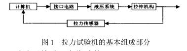
The entire Tensile Testing Machine is mainly composed of five parts: computer system, interface circuit, hydraulic system, tensile mechanism and tensile sensor, as shown in Figure 1.
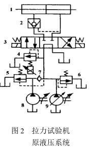 At the beginning of the test, first fix the test piece on the tensile mechanism, and then operate the computer to input various test parameters and print the required content of the report, including the test piece model, test name, set tension, etc. The computer runs the test program, drives the electro-hydraulic proportional valve and the reversing valve through the interface circuit, so that the hydraulic cylinder 1 generates the required tensile force, and at the same time, the computer collects the force value fed back by the sensor in real time, compares it with the set force value and Complete the corresponding control algorithm. According to the actual test requirements of the test piece, two working modes are set on the testing machine: the first is the rated load test, which is to maintain the pressure for a period of time when the test piece is stretched to the set force value, and then unload; the second is the rated load test. The second is a static load test, or a fracture test, in which a uniform force is applied to the specimen until it breaks or is destroyed. The hydraulic circuit principle of the original system is shown in Figure 2. Two pumps connected in parallel (low-pressure pump 8 and high-pressure pump 9) are used to supply oil to the system, and relief valve 5 and relief valve 6 are used to adjust the low-pressure pump 8 and high-pressure pump respectively. 9 of the highest working pressure, of which 7 is a one-way valve. The working pressure of the system is adjusted by changing the overflow of the electro-hydraulic proportional valve 4. When the reversing valve 3 is in the left position, the pressure oil enters the left chamber of the oil cylinder 1 through the hydraulic control check valve 2, and the testing machine is in the tension working state; The test piece is under pressure.
2 Problems in the hydraulic system and corresponding improvements
After analyzing the principle of the original system, combined with long-term use and maintenance experience, the following three aspects of the system have been properly improved and designed.
(1) Improvement of pressure holding circuit
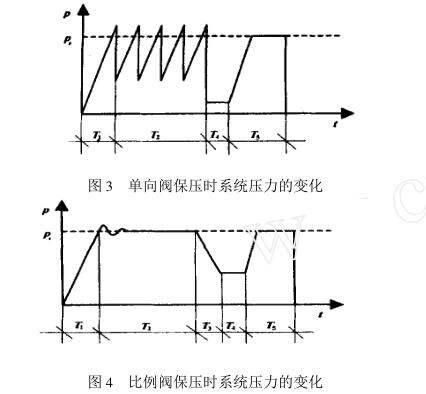
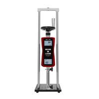
It can be seen from Fig. 2 that the original system uses the hydraulic control check valve 2 to maintain pressure . When the rated load test is carried out, when the tension of the oil cylinder reaches the set tension of the specimen, the reversing valve 3 is switched to the neutral position, and at the same time the The electro-hydraulic proportional valve 4 is in the unloading state, and the system pressure at this time is approximately zero, and the hydraulic cylinder relies on the hydraulic control check valve 2 to close the pressure oil in the left chamber to maintain pressure. Since both the oil cylinder and the one-way valve have a certain leakage, and the specimen will also have a certain deformation and slippage, the pressure of the oil cylinder will drop faster with this pressure maintaining method, and the test tension of the specimen is required to be more accurate. (the error is not more than ±2%), and the pressure holding time is relatively long (5~30min), so during the whole pressure holding process, the hydraulic control check valve, reversing valve and electro-hydraulic proportional valve act repeatedly, frequently Cylinder replenishment booster. In this way, the pressure of the system is in a large and violent change, and each component is in a state of frequent shock and vibration, which is one of the main reasons for the damage of the hydraulic system. Therefore, in the new hydraulic system, the hydraulic control check valve is removed, and the electro-hydraulic proportional valve is used for continuous control to achieve pressure maintenance, so that the system pressure changes smoothly, and each component is in a relatively stable working state, which greatly improves the reliability of the system. sex. Figure 3 and Figure 4 respectively illustrate the change of system pressure in the two schemes. Among them, Ps is the set tensile force of the rated load test, T1 is the pressurization time, T2 is the pressure holding time, T3 is the unloading time of the specimen, T4 is the reversing time, T5 is the reset time of the oil cylinder, comparing the two figures can be It can be seen that the system pressure of the former fluctuates greatly, and the system pressure of the latter is relatively stable during the pressure holding period; in addition, at the end of the pressure holding, the former reduces the pressure to the minimum suddenly, and the reversing valve immediately changes direction. When the piston of the oil cylinder is pulled by the elastic force of the test piece, it will produce severe impact and crawl, which is very easy to damage the seal of the oil cylinder; while the latter is to gradually drop the pressure at the end of the pressure holding, so that the elastic force of the test piece slows down. Released effectively, effectively protecting the cylinder.
(2) Improvement of electro-hydraulic proportional valve part
In the original system, another weak link is the electro-hydraulic proportional valve, its spool is easily stuck, and its dynamic response is relatively slow. In order to improve the system's real-time control accuracy and work reliability, it was decided to adopt the electro-hydraulic proportional valve produced by German Rexroth Company. 2L/min, medium temperature range -20~80℃. After using the valve, better dynamic response characteristics were obtained under the same control program. After two years of use, it has been proved that the valve has high reliability.
(3) Improvement of fuel tank part
The effective volume of the oil tank in the original system is not enough to adapt to the high-temperature climate and all-weather working conditions in southern summer. During long-term use, the oil temperature rises too high, the leakage of the system increases, and the seals are often damaged. After calculation, the reasonable effective volume of the fuel tank should be 2818L, while the original effective volume is about 20L, which obviously cannot meet the requirements. At the same time, considering the requirements of oil precipitation and filtration, the effective volume of the oil tank is finally increased to 35L.
3 Conclusion
Since hydraulic technology is a very professional technology, once the equipment breaks down, it is very difficult for the user to repair it by himself, so the user is most concerned about the reliability of the equipment. The 500kN hydraulic Tensile Testing Machine in this project has been through the technical transformation of the above aspects, eliminating the impact phenomenon, reducing the vibration and noise during work, so that the equipment can run in a good state, the reliability of the system and the life of the components There has been a great improvement. The equipment has been in normal operation for two years since it was put into use after transformation, and the hydraulic system has not had any failures . The user is very satisfied with this.


- 1Tensile machine application in various industries
- 2Technical analysis of key parameters of Tensile machine: Scientific selection from force measurement accuracy to Power system
- 3Tensile machine purchasing guide [dry version]
- 4Talking about the performance test of epoxy resin film coated on PET
- 5ASTM D5019 Single-layer roofing film reinforced CSM board (chlorosulfonated polyethylene (PE)) standard interpretation
- 6Common problems and solutions in tensile testing
- 7What is tensile strength testing and which products can be tested?
- 8Factors Affecting the Performance and Accuracy of Tensile Testing Machines
- 9Classification of Tensile Testing Machines
-
![Patek Jushi LY-7012C Tensile Tester 1000KG]()
-
![BaidaJUSHI LY-7012A Small Tensile Testing Machine 200KG]()
-
![CHINA NBC-1024-2 Tensile Tester 5T]() CHINA NBC-1024-2 Tensile Tester 5T$ 6586.00
CHINA NBC-1024-2 Tensile Tester 5T$ 6586.00 -
![CHINA NBC-6820 Ring type initial tacking machine Tensile Tester]()
-
![CHINA NBC-1023-1 Computerized Double Column Tensile Testing Machine]()
-
![CHINA NBC-1021 Touch screen single column Tensile Strength Tester 10KG]()