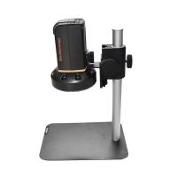
FTN-430/450 Desktop Microscope Simple Manual
1. Microscope function introduction:
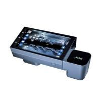
1. Front panel function introduction (FTN-450/FTN-430 front and rear panels are the same)

2. Rear panel function introduction

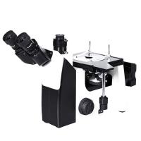
2. 0FTN-430/450 standard kit:

Three, 0FTN-430/450 optional accessories:
1. Common optional parts for FTN-430 and FTN-450

2. FTN-450 special option - multi-core special fixture

4. Operating Instructions
1. Install the ferrule fixture adapter first according to the test requirements
(1) Install 2.5mm or 1.25mm adapter head

2) FTN-450 type installation multi-core adapter head
According to the test needs, fix the adapter heads of different specifications on the test head seat with a hexagonal screwdriver, as shown in the figure below:

2. Adjust the focus until the image is clearest
2.5mm or 1.25mm ferrule, because of the different focal length position, need to adjust the focal length
3. Adjust the X axis or Y axis, FTN-450 can check any part of the ferrule
(1) Single core can be inspected, any part of the surface of the ceramic ferrule except the fiber end face
(2) Can inspect 2-core MTRJ, 4-core to 48-core MPO ferrule and panda fiber ferrule
4. It can check the light hole to prevent the defective products that block the light hole from passing through
5. Switch control and connection

1. Connection with LCD
(1) Connect the two ends of the five-pin plug-in cable to the five-pin socket of the 10.4-inch LCD monitor and the five-pin socket at the end of the end face inspection instrument respectively.
(2) Turn on the main switch on the rear panel of the display, and the display and the FTN-430/FTN-450 microscope will start to supply power at the same time. The switch on the rear panel of FTN-430/FTN-450 can independently control the power supply of the microscope. When the switch is turned off, the microscope stops working and the display is still in standby mode.
Note: Five-pin aviation plug is connected to the monitor. Installation instructions:
(1) Correct connection method: Hold the aviation plug at the end of the Detector firmly, align it with the five-pin interface on the back of the display, rotate the connector in your hand to find the corresponding bayonet, and then press firmly to connect successfully, as shown in the figure below:

(2) Remove the five-pin aviation plug from the monitor:
The correct method of operation is: firmly grasp the snap ring of the grooved part of the aviation plug, and pull out the plug vertically downward. As shown in the picture:
Wrong method of operation: Do not hold other places to pull out, this method of operation will not remove the plug, and may damage the accessories. As shown in the picture:

2. Optional function: use FTN-430/FTN-450 microscope on 9-inch monitor
(1) When using the microscope on a 9-inch desktop monitor, it is necessary to use the FTN-430/FTN-450 dedicated power adapter to provide additional power for the microscope.
(2) Please use the BNC cable (BNC video signal mode) to connect the microscope and the desktop microscope.
3. Connect to a computer via a USB port (option) for image observation and analysis
(1) Use the special USB connection jumper to connect the end face inspection instrument to the computer, and the front USB light will light up.
(2) Set the power switch of the end face inspection instrument to the USB position, the front power light is on, and the end face inspection instrument can start to work.
(3) Press the power switch to the left, the 12V power supply works; press the switch to the right, you can use the USB function; press the switch to the middle position to turn off the power.
(4) Introduction to the function of the USB function software US20 data image processor
The US20 processor uses rich software functions to capture, record, amplify, and adjust the brightness of fiber optic images on the computer. The language of US20 operation interface can be selected from multiple countries, such as Chinese, English, German and so on. The software operating instructions are described in detail in the CD-ROM in English.
The US20 processor is a multifunctional video signal data player. Among the many functions, we only choose the useful functions of optical fiber images. The rest do not need to operate.
The computer interface of the US20 processor is a 2.0-level USB, which is compatible with a 1.0-level USB interface for computer communication.
6. Matters needing attention
1. If the adapter is used for too long, the jack will wear out to a certain extent. When the adapter socket cannot position the ferrule, the adapter needs to be replaced.
2. Pay attention to the cleanliness of the fiber optic microscope lens, reduce the pollution of dust and fiber residue, and prolong the service life.
Seven, after-sales service
1. Please check and accept the goods within three days after receiving the goods. If you find any problems, please contact the supplier in time.
2. The warranty period is 36 months, long-term maintenance.
3. The manufacturer will not bear the warranty responsibility for damage caused by improper use (such as: knocking) and self-disassembly.


- 1Microscope classification, operation and application
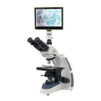
- 2How to use trinocular Microscope
- 3How to detect the color difference of fluorescent color-changing materials?
- 4How is the content of non-fibroblasts determined?
- 5 How to measure cell wall thickness and cell cavity diameter?
- 6Determination of Fiber Length How is the distribution frequency calculated?
- 7How to determine the fiber morphology of plant fiber raw materials?
- 8Important instruments in clinical laboratories
- 9Coating Thickness Gauge: How to measure the dry film thickness of non-metallic substrates?