Flash point measuring method and flash point measuring instrument
1. Scope and Description
This method is suitable for the determination of the flash point of paints and varnish products. The measurement range of the flash point is below 110°C. The measured results of mixed solvents containing halogenated hydrocarbons have abnormal phenomena. The flash point (closed cup) in this method refers to the lowest temperature at which the escaped vapor can flash instantly in the presence of a flame when a sample in a closed cup is heated under specified conditions.
Note: The flash point of this method should be 101.3kPa according to the standard atmospheric pressure.
2. Apparatus and Materials
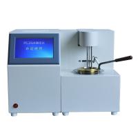
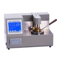
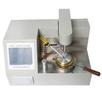
(1) The flash point Tester is shown in Figure 1-27. The instrument consists of a test cup, a test cup cover, a heating device, a cooling device and a timing device.
① Test cup. Constructed of brass or other suitable heat-conducting, corrosion-resistant metal block. On the upper part of the metal block, there is a test groove with a cover and a diameter of about 50mm and a depth of about 10mm. The thermometer is inserted into the thermometer hole of the metal block. Figure 1-28 is its plan view. "

② Test cup cover. Made of brass or other suitable metal about 2mm thick. It is equipped with a switchable slide plate (made of stainless steel or other suitable metal with a thickness of about 1.2mm. Generally, an electric device is used, and a manual device is also installed) and when the slide plate is opened, the test flame [diameter is (3.5 ± 0. 5) mm] The ignition device extending into the groove of the sample. When the flame extends in, the nozzle opening of the test flame shall be ±0.1 mm from the bottom surface of the test cup lid. There is also a small hole extending into the groove of the sample on the cover to accommodate the sample. In order to ensure the tight combination of the cover and the test cup, appropriate clamps can be used to make the centerlines of the three holes on the cover coincide with the diameter of the sample groove. When the slider on the cover is in the open position, the two holes on the slider need to coincide exactly with the corresponding two holes on the cover.
③Heating device. It adopts electric heating and is equipped with a temperature controller, so that the temperature of the metal block can be controlled within the required temperature range of 0.2°C.
④ Cooling device. It is cooled by semiconductor refrigeration elements.
⑤ Timing device. Using digital tube timing.
(2) Ammonia-filled mercury glass thermometer placed horizontally with a suitable range, with a minimum division of 0.5°C, suitable for insertion into the thermometer hole of a metal block. The maximum error in measuring the temperature of the test cup should not exceed 0.5°C. During the test, first coat a layer of thermoplastic material with good thermal conductivity, and then insert it into the manhole.
(3) The volume of the syringe is 2mL, accurate to ±0.1mL. For high viscosity products, a spoon can be used.
(4) The fuel of the ignition device is usually butane, but coal gas or natural gas can also be used.
3. Measurement method
(1) Method 1 is applicable when the estimated flash point is from room temperature to 110° C (method 2 is recommended if the expected flash point is close to room temperature).
① Cool the sample and sample container to 10°C lower than the estimated flash point.
②Ensure that the sample groove, cover and sliding plate are dry and clean, cover the cover, and close the sliding plate.
@Turn on the heating device, when the temperature reaches 3°C lower than the expected flash point of the sample to be tested, slowly adjust the controller of the heating device until the sample groove reaches the expected flash point temperature and remains stable.
③ Use a dry and clean syringe to absorb 2mL of the cooled sample, and quickly inject the sample into the sample groove through the feeding hole. Be careful not to cause any loss of the sample. Withdraw the syringe and immediately start the timer.
Note: If the viscosity of the sample to be tested is high and it is difficult to inject through the feeding hole, you can open the lid and use a spoon to pour 2-3mL. The sample is added to the sample groove, and after the sample is taken out, the sample container should be tightly covered and put back to a place 110°C lower than the expected flash point.
④Open the gas control valve, ignite the test flame, and adjust the flame into a spherical shape so that its diameter is (3. 5±0.5) mm.
⑤After 60s, the test temperature can be considered to have been reached. Open the slide plate, reach out and remove the flame nozzle, close the slide plate, complete an ignition test, the time is (1.5±0.5)s, and observe the flash fire during the period from opening to closing of the slide plate.
⑥Record whether flash fire occurs.
Note: a. When the gas mixture of the sample vapor in the test is close to the flash point, the ignition will produce a halo, but only when a relatively large blue flame appears and spreads to the entire liquid surface, the sample can be considered to have flashed .
b. When the slide is turned on to ignite, if a continuous bright flame is observed at the hole, it indicates that the flash point is lower than the test temperature.
⑦ If no flash fire is observed, the test is to be carried out again with a fresh sample every 5°C within the temperature range higher than the previous measuring point, until a flash fire is observed. If a flash fire is observed, re-test with a fresh sample every 5°C within the temperature range lower than the previous measuring point until no flash fire is observed. Once the sample has been subjected to the ignition test, the test shall be terminated and a fresh sample shall be taken for each subsequent test.
⑧ Between the two temperatures with a 5°C interval between the flash fire and the non-flash fire, and then use a new sample to start from a lower temperature, and carry out the test according to the above steps at intervals of 1"C until observed Flash fire. In the event of a flash fire, read the thermometer to the nearest 0.5"C and record the result. This value is taken as the flash point of the sample under the atmospheric pressure at the time of the test, and the atmospheric pressure expressed in kPa, mbar or mmHg is recorded at the same time.
⑨ Repeat the measurement and calculate the arithmetic mean of the corrected flash point, accurate to 0.5°C.
Note: After each ignition test is completed, the gas control valve needs to be closed, and the sample groove and cover should be cleaned immediately.
(2) Method 2 is applicable when the expected flash point is below room temperature.
① Cool the sample and sample container to 3-5°C lower than the expected flash point. During the test, the instrument should be passed through cooling water first.
② Cool the sample groove, slowly adjust to the expected flash point temperature, and keep it stable. The specimen well should be dry and clean with the slide closed.
③Use a dry and clean syringe to absorb 2ml of sample, and quickly inject the sample into the sample groove through the feeding hole. Be careful not to cause any loss of the sample, pull out the syringe, and start the timer immediately.
Note: If the viscosity of the sample to be tested is high and it is difficult to inject people through the feeding hole, you can open the lid and use a spoon to pour 2-3mL. Put the sample into the sample groove. After taking out the sample, cover the sample container tightly and put it at a place 10°C lower than the expected flash point.
④Open the gas control valve, ignite the test flame, and adjust the flame into a spherical shape with a diameter of (3.5±0.5)mm.
⑤After 60s, it can be considered that the sample has reached the test temperature. Open the slide plate, extend and remove the flame nozzle, close the slide plate, complete an ignition test, the time is (1.5±0.5) s, and observe the flash fire during the period from opening to closing of the slide plate.
Notes: a. When the test sample vapor mixture is close to the flash point, the ignition will produce a halo, but only when a relatively large blue flame appears and spreads to the entire liquid surface, the sample can be considered to have flashed .
b. When the slide is turned on to ignite, if a continuous bright flame is observed in the hole, this indicates that the flash point is lower than the test temperature.
①Close the gas control valve, and clean the sample groove and cover.
②Record whether flash fire occurs.
③ If no flash fire is observed, within the temperature range higher than the previous measuring point, re-test with a new sample every 5·c until a flash fire is observed. If flash fire is observed, within the temperature range lower than the previous measuring point, the test shall be carried out again with a new sample every 5°C until no flash fire is observed. Once the sample has been subjected to the ignition test, the test shall be terminated. Each subsequent test shall take fresh specimens.
④Between the two temperatures with a 5°C interval between the flash fire and non-flash fire determined, start from the lower temperature with a new sample, and carry out the test according to the above steps at intervals of 1°C until a flash fire is observed. When a flash fire occurs, the thermometer shall read to the nearest 0.5°C and record the result. This value is taken as the flash point of the sample at the atmospheric pressure at the time of the test, and the atmospheric pressure expressed in kPa, mbar or mmHg is also recorded.
⑤ Repeat the measurement and calculate the arithmetic mean of the corrected flash point, accurate to 0.5°C
Note: a. Before the test, the sample should be placed in a closed container, and the empty volume in the container should exceed 10% of the entire container, and the sample should not be stored in plastic (such as polyethylene, polypropylene, etc.) bottles. After the sample is taken out, the sample container should be tightly closed immediately to ensure that the loss of volatile components in the container is minimized. Otherwise, the sample is no longer suitable for testing.
b. In case of dispute, the test shall be carried out under the conditions of (25±1)℃ and relative humidity of 60%-70%.
4. Reference standards
National standard GB/T 5208-2008