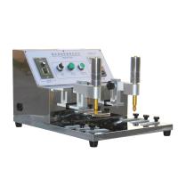
NORMAN RCA7-IBB Wear testing machine
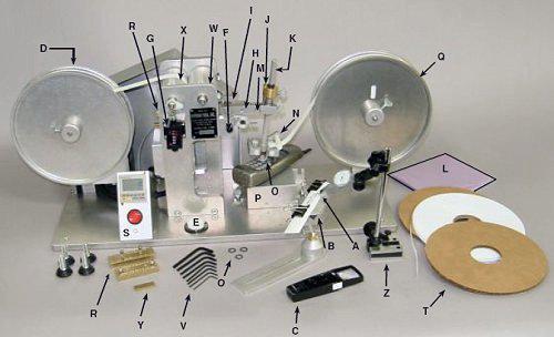
RCA paper tape abrasion machine parts diagram
Description of paper tape grinding machine parts:
A. Universal sample holder
B. Universal clip-on sample holder
C. Magnifying glass with light
D. Winding reel device
E. Spirit level, used to adjust the level of the machine
F. Sliding bolt, used to confirm whether "H" is parallel to the base of the instrument, and set "Z" (surface gauge, indicating parallel to the instrument). When the "O" ring and test paper are placed in the test area, it is necessary to confirm whether In line with parallel, the sliding bolt must be moved out from under the rocker arm "H" during operation.
G. Revolution counter
H. Swing arm
I. Cam shaft screw
J. Vertical axis fine adjustment screw
K. Vertical axis, the position can be adjusted
L. Dust cover
M. Clamp screw on swing arm (used to change vertical axis angle)
The angle of the vertical axis has been fixed before leaving the factory, please do not loosen the adjustment at will, please refer to the precautions.
N. Nylon paper guide roller frame, used to guide paper and tape without any adjustment.
O. O-rings, worn flat or need to be replaced after six months of use.
P. Sample stage, to hold flat samples
Q. Aluminum supply reels with 11/16” wide abrasive tape (Federal Spec. # UUT00126E)
R. Two weight reduction weights are installed on the left rear part of the rocker arm, so that the sample can bear a load of 55 or 175 grams.
S. Electronic Counter
T. 1/4" wide abrasive tape (RCA tape) for testing concave and elongated letters
U. to be determined
V. Hex wrench set
W pressure roller
X drive roller
Y 1/8 Thick Sheets (in an accessory box)
Z surface gauge to indicate that the sample is parallel to the surface of the instrument base
RCA Tape Machine Counter Quick Start Guide
NOTE: It is recommended to use mechanical counters until you are familiar with electronic counting controls.
To read the counter after the sample has been tested:
Press the "Mode" key, then press 6 repeatedly until "du" appears. This is to set positive count. If you want to set the countdown, press this key again until "d" appears
Note: You can press the "Mode" button repeatedly to switch between the two modes of "d" or "du" (counting up or counting down).
1. Set the red ON/OFF switch to the "OFF" position.
2. Plug in the test cord
3. Press the "Mode" key to confirm "d" or "du"
4. Immediately press the "Display" button once
5. Press the number keys until the desired number of laps appears on the Display.
6. Press the red ON/OFF key to the "ON" position to start the test.
7. 在达所设定的数字前随时按红色按钮可停机查看测试结果。当重新开始测试时以前累计的数字不会丢失。
8. 重新启动机器后,机器运转到设好的数字时会停止。
9. 再按"reset"按钮可开始下一个和先前设置一样的测试或者继续测试到一个比先前更高的设定数字。
注意:在使用"reset"键和”红色” 开关键时,手动计数器也可用于计数
建议:可设置高于要求的数字,通过使用红色on/off开关键控制马达。
7-IBB/7-IBB-CC纸带磨耗机安装和操作
漆层表面性能即时磨耗测试
请确保磨耗介质上不含残留物质进而保证测试的准确性
重要注意事项:
导纸轮框架(N)中之4个尼龙轴承不能夹住纸张边缘。
同样地,供给卷轮'Q'亦不能防碍纸带或胶带之转动
在每天使用之前先取下O形环组合,清理O形环中心轮、轴承及其他所有接触的表面。
参考表面计页。
磨耗带宽度作调整时,只需要取出或放进位于前后卷轮'Q' 、'D '上的垫圈' T' 使磨耗带固定在机子上。#977机或更高机子则不须如此操作。
两个重量砝码'R' (55g和175g)用来测试热印式亮光薄膜,或者其它软性漆体测试。
当使用1/4"带宽时,如果你发现磨耗纸带磨面一边偏出卷轴,那么将带子扭到磨面朝下,不要磨带子的光面一边。
注意:用带子的哑面磨3倍于光面磨的效果。但也有不同的看法。
机器底座通过观察水平仪并调整垫脚螺丝来调平。
测试样品的安装
1. 滑动栓(F)移动至摇动臂下方,当凸轮接近最低位置时停止马达,摇动臂支撑于滑动栓上。
注意:凸轮与凸轮随动轴之间需要有空隙,摇动臂与滑轮栓之间不能有纸张。
2. Fix the parallel plate sample on the sample platform (P) with single-sided or double-sided tape, or use the attached clip to fix the sample on the anvil (P). Fix samples with non-parallel surfaces with the roller plate sample holder (A). Fix the round sample with the vise-type sample holder (B) (the flat plate on the roller plate-type sample holder must be removed first). When fixing the sample in the above way, it is necessary to use the surface meter (Z) to adjust the surface to be tested to be in a parallel state.
3. Lower the vertical shaft (K) (please loosen the two fixing screws first), so that the wear test material is tightly located between the O-ring samples, and then tighten the two fixing screws by hand, and move the vertical shaft (K) upwards ), you can lightly press the spring before moving, do not press the O-ring or raise the rocker arm.
4. Move the slide pin (F) out from under the swing arm (H).
5. Hold and raise the swing arm (H) to prevent the paper from contacting the sample, jog the motor until the cam supports the swing arm (H) and the paper is not on the sample.
6. The counter (G) is reset to zero.
carry out testing
Start the motor, and when the rocker arm is in the raised position, check whether the test area is worn to the substrate (whether the control color is different), this method is suitable for the standard rotary test. If continuous wear test set, stop motor to view results
- 1Introduction to common wear resistance test methods
- 2Principle, Application and Selection of Adhesive Tape Wear testing machine
- 3Briefly introduce the working principle, application and selection precautions of rubber Wear testing machine
- 4Basic Principle and Application Analysis of Asphalt Wear testing machine
- 5Basic Principle and Application of Lubricating Oil Wear Resistance Tester
- 6Demonstration of RCA wear-resistant tape machine
Air - 《南北潮》
- 7The principle, application, operation and selection of wear-resistant testing and wear-resistant testing machines
- 8How to extend the service life of rubber?
- 9Briefly describe how different industries view product packaging