Development process of graphic analysis magneticstirrer
The article mainly introduces a magnetic stirrer driven by digital signals based on the design of 89C51 single-chip microcomputer. The most prominent advantage of the intelligent digital magnetic stirrer is its low-speed stirring performance and stable speed performance characteristics, which improves the high-precision constant temperature System stability. The application effect of the intelligent digital magnetic stirrer in the solution chemistry experiment device is very good.
The magnetic stirrer is a common solution component in scientific research and production. The traditional magnetic stirrer commonly used at present basically uses an AC series-excited motor, and the speed adjustment is realized by adjusting the AC voltage; because the speed of the AC series-excited motor varies with the torque and power supply The voltage changes greatly, and when the experimental process or external factors affect the physical properties of the experimental system, such as the viscosity coefficient of the solution, there will be a large speed error, or even stop; in addition, because the traditional magnetic stirrer does not have intelligent , the abnormal situation cannot be dealt with in time, which has caused great harm to scientific research and production. To meet the needs of scientific research, we have developed a magnetic stirring part that uses 89C51 single-chip microcomputer to generate digital control signals to drive stepper motors, and then the stepper motors drive new powerful NdFeB magnets. It fundamentally solves the defects of large speed error, small torque and poor low-speed performance of the traditional magnetic stirrer, and the use effect is good.

Fundamental
This machine is mainly divided into hardware and software. Hardware is the basis for system operation. This design adopts the 89C2051 single chip microcomputer of ATMEL company as the core, and uses the stepper motor as the transducer element, which provides a guarantee for the system's operation accuracy and intelligence. Software is the soul of system operation. The software adopts the method of reading the user-set parameters in real time and correcting the driving signal of the stepping motor, and monitors the rotation state of the stepping motor through the Hall sensor, monitors the abnormal situation, corrects and handles it in time, and achieves accurate and timely , The goal of long-term stable stirring rate control.
Introduction to hardware circuit
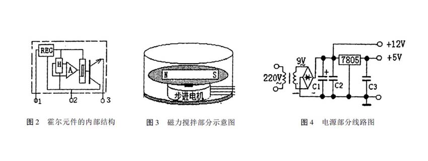
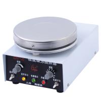
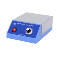
The hardware circuit of this machine is composed of control part, isolation and amplification part, execution part, feedback detection part and power supply part and other units. The hardware circuit structure is shown in Figure 1. The basic working process is as follows: 89C2051 MCU reads the setting values of two decimal code switches from port P1, generates 2 channels of fixed-width FM timing pulse control signals according to the setting values, and the 2 channels of timing pulse control signals pass through ports P3.4 and P3. .5 ports are respectively sent to the photocoupler IC3 and IC4 for isolation, and then amplified by the power drive circuit to drive the stepping motor; the rotation of the stepping motor is detected by the Hall sensor IC2, and fed back to the P3.4 port of the single-chip microcomputer to judge the stepping The running state of the motor; if the stepper motor is not running properly, the buzzer (FM) will be driven from the P3.0 port to send out a 5-minute intermittent alarm signal, and at the same time, the P3.1 port will send out a fault indication signal. The internal structure of the Hall element is shown in Figure 2. The schematic diagram of the magnetic stirring part is shown in Fig. 3 . The bar magnet adopts a new type of neodymium iron boron strong magnet. The power supply part is shown in Figure 4.
Software Description
The software of this machine adopts the query mode to work. By reading the 8-bit data of the dial switch in real time, the speed of the stepper motor is adjusted by modifying the duty ratio of the stepper motor in the way of fixed width frequency modulation, and after each step signal is sent out, by detecting The feedback signal of the Er element can be used to monitor the rotation state of the stepper motor
the goal of. The software process is shown in Figure 5.
Instructions
When using this machine, the host part should be placed in a dry and ventilated place, and the ambient temperature of the stirring part should not be higher than 150°C; when stirring at high speed, a magnet with strong magnetism should be used to ensure the torque required for stirring. In addition, when the main engine is used in a high-precision system, the stirring speed should be correctly selected to reduce the system temperature error caused by the conversion of stirring energy to work and heat.
discuss
Since this machine is a component specially developed and designed for scientific research projects, there are certain limitations. However, its characteristics of high rotational speed accuracy, large torque and good low-speed performance are incomparable to traditional magnetic stirrers. In the future work, we will further take advantage of the single-chip microcomputer to develop a low-cost, multi-functional new magnetic stirrer that can be programmed to achieve multi-time, multi-speed, and has speed display and can drive multiple stirring parts.


- 1Comparison and Application of Magnetic Stirring and Mechanical Stirring
- 2Application and Selection Guide of Electromagnetic Stirrer in Laboratory
- 3Describe 4 Common Stirrers in detail
- 4Principle and Application of Water Bath Magnetic Stirrer
- 5What is a mixer? Applications, advantages and disadvantages of mixers
- 6How to prepare polymer blended solid film materials?
- 7Agitators and their classification
裴梦琛 - 《西北大学》
- 8Testing Factors Affecting the Drying Properties of Plastic Water-based Gravure Ink with Agitator
- 9What are the characteristics of an overhead mixer?
-
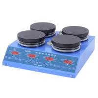
![DaDi 85-2 digital temperature control magneticstirrer]()
-
![HUXI HMS-203D magneticstirrer]() HUXI HMS-203D magneticstirrer$ 249.00
HUXI HMS-203D magneticstirrer$ 249.00 -
![Qiwei CL-R magneticstirrer 1000ml]() Qiwei CL-R magneticstirrer 1000ml$ 102.00
Qiwei CL-R magneticstirrer 1000ml$ 102.00 -
![DADI CJJ78-1 Magnetic Stirrer]() DADI CJJ78-1 Magnetic Stirrer$ 100.00
DADI CJJ78-1 Magnetic Stirrer$ 100.00 -
![RONGHUA HJ-6 Six Head Magnetic Heating Stirrer]()
-
![RONGHUA Instrument 99-1A Dual digital display high power thermostatic magnetic heating Stirrer]()