Understand the meaning of surface roughness symbols
Use symbols to represent surface textures of mechanical and structural parts in industrial drawings. Graphical representations using these symbols are defined in ISO 1302:2002.
This article explains how to write these symbols to indicate surface texture.
1. Terminology Explanation
Surface Texture: This is an umbrella term for factors such as roughness, necessity of removal machining, crease direction, and surface relief of mechanical and structural parts.
Removal Machining: This refers to the removal of surface layers from a part by machining or similar methods.
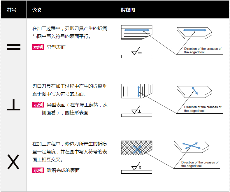
Crease Direction: This is the direction in which to remove the sharp creases formed during machining.
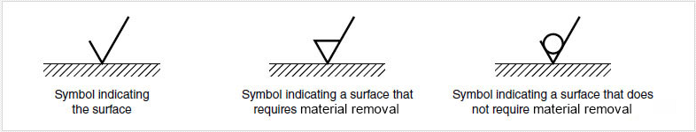
2. Symbols indicating the target surface and the location of these symbols
When representing surface texture graphically, the symbol representing the surface of interest is represented by two lines of different lengths with an angle of 60° between them.
This surface roughness indication method displays information such as surface roughness value, cutoff value, sampling length, processing method, crease direction sign and surface waviness on the surface indication symbol as shown in the figure below.
a: sign and value of passband or sample length and surface texture parameters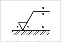
b: indicates the second and subsequent parameters when multiple parameters are required
c: processing method
d: crease and its direction
e: machining allowance
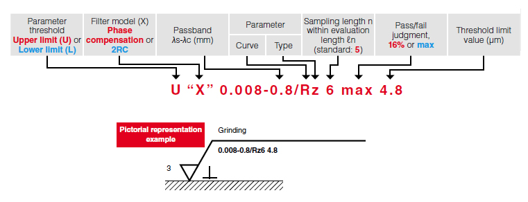
When graphically representing surface roughness, the descriptors shown below are used. In general, however, the standard conditions shown in red are omitted, and the indications shown in blue are included only when necessary.


- 1High-precision roughness instrument measures the surface roughness of plastic materials Case sharing [Video demonstration]
- 2The relationship between abrasive and surface roughness
- 3Surface roughness of metal
- 4Roughness and Surface Roughness
- 5Which industries need to use surface roughness meters?
- 6Surface roughness measurement
- 7What are the application fields of surface roughness meter?
- 8What are the main manifestations of the influence of surface roughness on parts?
- 9What data is the surface roughness mainly evaluated by?