Specific measurement method of needle type surface roughness meter
Step 1 Locate the measurement target.
Remove any oil or dust from the surface of the measurement target.
If the measurement direction is not indicated, position the target so that the measurement direction has maximum parameters in the height direction (Ra, Rz).
STEP2 Visually inspect the target surface.
Determine whether the object's surface texture (creases, roughness profile) is periodic or non-periodic.
When step 3-1 graphically represents the sample length
When the sampling length is indicated on the graph or in the requirements of the product's technical information, the cutoff value λc is set to the indicated sampling length.
Step 3-2 When the roughness profile is periodic
1. For a target surface with a periodic roughness profile, estimate the parameter RSm from the measured principal profile.
2. Determine the corresponding sampling length (cutoff λc) from Table 1 using the estimated RSm.
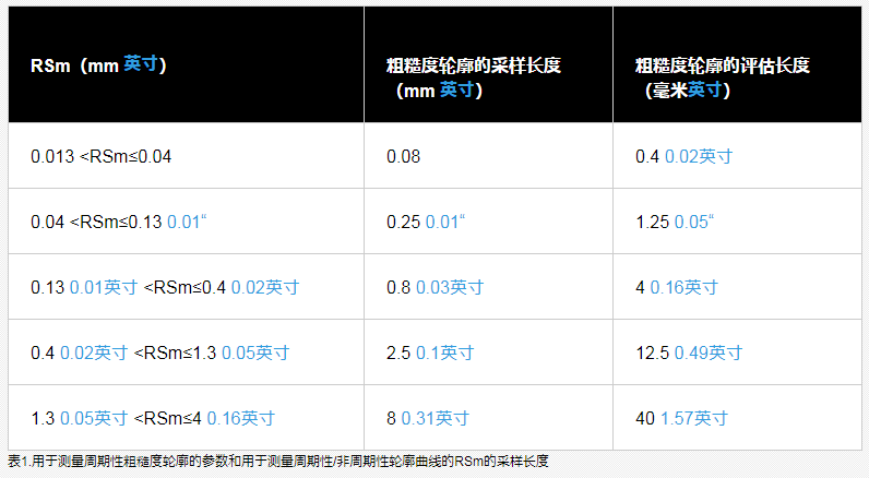
3. Measure the RSm value using the determined sample length.
4. When the measured RSm is within the range of RSm estimated in Table 1, the cut-off value is used. When the measurement is outside the estimated RSm range, change the cutoff value to the sample length of the corresponding RSm.
5. Use the sample length determined so far to measure the desired parameter.
Step 3-3 When the roughness profile is not periodic
1. For a target surface with a non-periodic roughness profile, estimate the unknown parameters Ra, Rz or RSm from the measured main profile.
2. Determine the corresponding sampling length (cutoff value λc) in Tables 1 to 3 by using the estimated unknown parameters Ra, Rz or RSm.
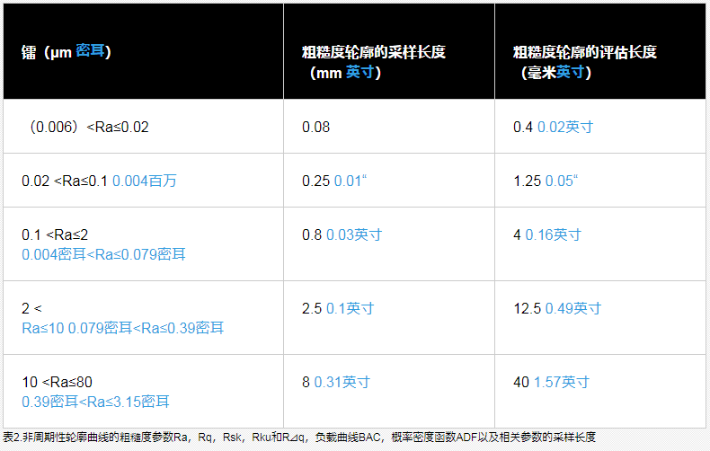
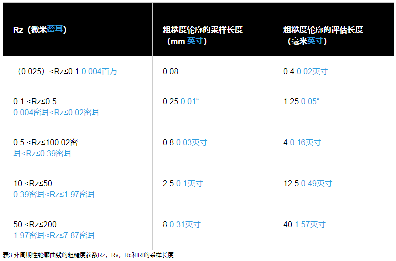
3. Use the determined sampling length to measure the value of the roughness parameter.
4. Use cutoff values when measurements are within estimated Ra or Rz ranges from Table 1 to Table 3. When the measurement is outside the estimated Ra or Rz range, change the cutoff value to the sample length of the range corresponding to the measured Ra or Rz.
5. Use the sample length you determined in step to measure the desired parameter.
STEP4 judges whether the parameter is within the threshold limit range according to the measurement result.
Use the visual inspection in step 2 to determine whether the target's surface texture is uniform (periodic) or varies in different locations (aperiodic).
Case 1: The target has a uniform surface texture.
Compare the measured parameters on the target surface as a whole with the desired values indicated in the drawing or in the product technical information. Then, judge whether the parameter is within the allowable range according to the 16% rule or the maximum value rule.
Case 2: The surface texture of the target is different in different positions.
Compare the parameters determined for each position on the object with the required values indicated in the drawing or in the product technical information. Then, judge whether the parameter is within the allowable range according to the 16% rule or the maximum value rule.
16% rule
When indicating the desired value as the upper limit of the parameter, please judge the position (Ra, Rz) with the maximum parameter in the height direction by visual inspection. Those parameters calculated from the entire sampling length cut from the obtained roughness profile (one evaluation length) exceed the required value by 16% or less are judged to be acceptable.
When expressing the desired value as the lower bound of the parameter, those parameters that are 16% or less less than the desired value calculated from the entire sample length (cut from one evaluation length) are judged to pass.
In more detail:
- The initial measured value does not exceed 70% of the indicated value.
maximum rule
When the required value shown in the drawing or in the product technical information is the maximum value, all parameter values determined from the entire area of the target surface are passed if the target value is less than or equal to the required value.

- 1Influence of surface roughness of parts
- 2High-precision roughness instrument measures the surface roughness of plastic materials Case sharing [Video demonstration]
- 3How to measure concrete surface profile (roughness) quantitatively
Defelsko
- 4Evaluation of steel surface roughness
- 5The relationship between abrasive and surface roughness
- 6Roughness and Surface Roughness
- 7Which industries need to use surface roughness meters?
- 8Surface roughness measurement
- 9What are the application fields of surface roughness meter?
-
![DUBAN DB20-SRT231 sand blasting shot peening Surface Roughness Tester]()
-
![Sand blasting shot peening Roughness Gauge AMITTARI AR-131A shot peening sand blasting, printing anti-corrosion and other industry tests]()
-
![KAIRDA NDT161 surface roughness Tester, contact asperity Tester]()
-
![KAIRDA NDT150A Surface Roughness Tester]()
-
![KAIRDA NDT151P Roughness Gauge]() KAIRDA NDT151P Roughness Gauge$ 810.00
KAIRDA NDT151P Roughness Gauge$ 810.00 -
![KAIRDA NDT151 Roughness Gauge asperity Measurement Instrument]()