Fangrui T series touch screen viscometer installation instructions
1. Take out the base, lifting column, viscometer host, host connecting rod, power adapter and other components in sequence from the packing box.
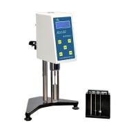
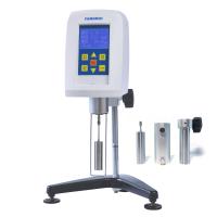
As shown in Figure 1, insert the lifting column into the hole of the base and tighten it with the nut (note: the lifting knob is placed on the right side), turn the lifting knob to adjust to a suitable lifting tightness, so that the host will not automatically slide down, and When lifting, the damping feel should be moderate. If it is too loose or too tight, it can be adjusted through the adjusting screw in front of the lifting slider.
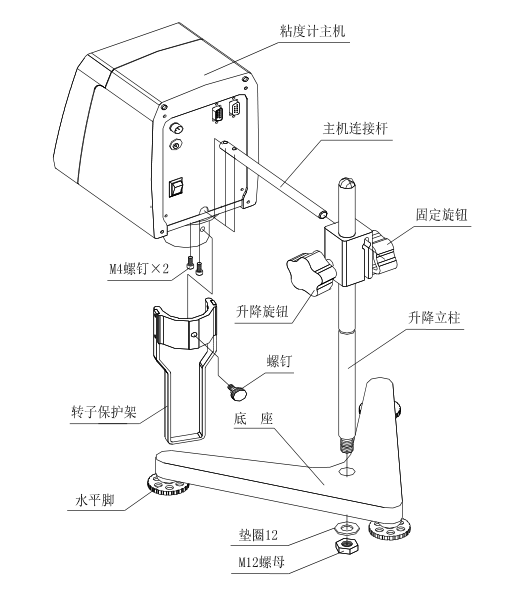
2. Unscrew the screw on the connecting rod of the main unit, and then insert the milling plane down into the installation hole at the rear and lower part of the main unit, and connect and fasten the connecting rod of the main unit to the bottom of the main unit with the unscrewed hexagon socket head screws. Then insert the host machine with the connecting rod into the installation hole of the lifting slider, and tighten the fixing knob after straightening.
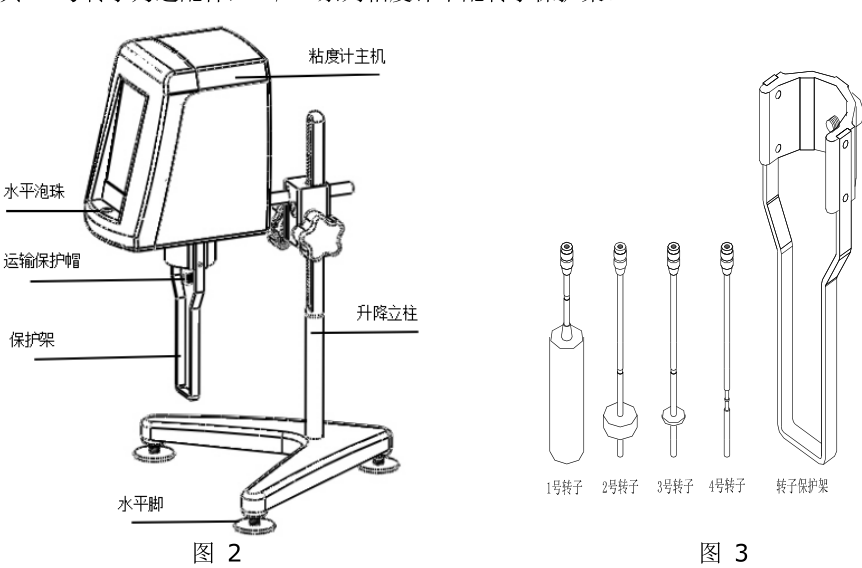
3. By adjusting the three leveling feet under the base, make the level bubble in front of the instrument be in the center of the black circle.
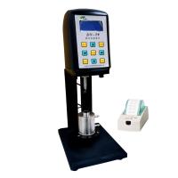
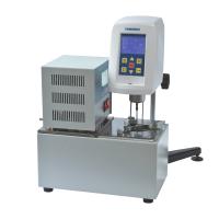
4. Take off the transport protection cap under the instrument cover, and turn on the power of the instrument. The appearance after assembly is shown in Figure 2.
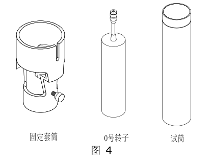
5. The structures of No. 1~4 rotors and rotor protection frame that come standard with the machine are shown in Figure 3.
6. The structure of No. 1~4 rotors of standard configuration of NDJ/SNB/LVDV series viscometer is shown in Figure 3.
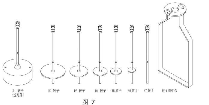
The structure of R1~R7 rotors of RVDV/HADV/HBDV series viscometers is shown in Figure 7.
The R1 rotor is an optional accessory, and the HA/HB series viscometers are not equipped with a rotor protection frame.
7. How to install and use No. 0 rotor (this part is optional)
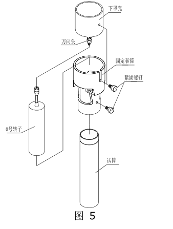
⑴ The No. 0 rotor part is composed of a fixed sleeve, a No. 0 rotor and a test cylinder. Its structure is shown in Figure 4. This part can only be used for the No. 0 rotor measurement, and it is not suitable for other rotor tests.
⑵ The installation of No. 0 rotor is as shown in Figure 5. First, rotate the No. 0 rotor clockwise (reverse thread) and install it on the rotor connecting screw (universal head).
⑶ Put the fixing sleeve on the cylinder of the lower cover at the bottom of the instrument from bottom to top, be careful not to touch the No. 0 rotor, and tighten it with the sleeve fixing screw.
⑷ Pour 20mL of the fluid to be tested into the test cylinder.
⑸ Put the test tube filled with fluid into the fixing sleeve gently from bottom to top until it rises to the top, and tighten it with the test tube fixing screw (note that the test tube should not touch the No. When tightening, it is necessary to pay attention to the tapered end of the test tube fixing screw so that it can be screwed into the triangular groove at the upper end of the outer wall of the test tube. All installed No. 0 rotor components are shown in Figure 6. After controlling the temperature of the liquid to be tested and adjusting the horizontal state of the instrument, the test can be carried out.
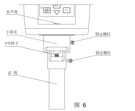
⑹ Note that the No. 0 rotor cannot be rotated without load when there is no fluid loaded, and the No. 0 rotor does not need to install the rotor protection frame when it is used.
8. Installation steps of SNB-1A-T viscometer rotor
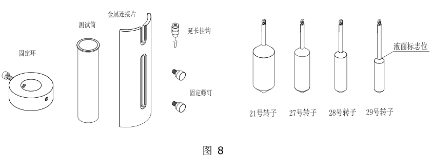
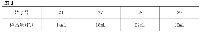
⑴ The SNB-1A-T viscometer rotor is composed of a fixed ring, a test cylinder, a metal connecting piece, an extension hook, a fixing screw and four rotors No. 21, 27, 28 and 29, as shown in Figure 8.
⑵ Prepare the sample to be tested and control the temperature of the liquid to be tested if possible. Pour an appropriate amount (see Table 1) of the tested sample into the test cylinder according to the selected rotor.
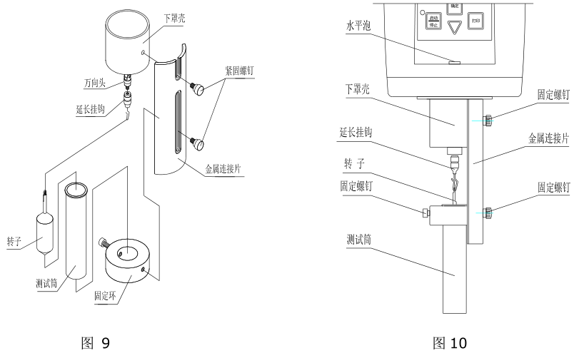
⑶ As shown in Figure 9, screw the rotor extension hook clockwise (reverse thread) into the universal joint, and select the rotor to be used according to the viscosity range of the sample and hang it on.
Note: When loading and unloading the rotor extension hook, it is necessary to lift the universal head up slightly to prevent damage to the rotating shaft tip
⑷ Put the test tube into the fixing ring, and tighten the screws on the side of the fixing ring.
⑸ Use fixing screws to fix the installed fixing ring and the metal connecting piece.
⑹ Fix the installed metal connecting piece and the lower cover of the main body of the viscometer with fixing screws. The installed parts are shown in Figure 10.
⑺ Adjust the immersion depth of the rotor so that the liquid level is just equal to the "liquid level mark" of the rotor. The liquid level mark is based on the uppermost end of the cone of the rotor. See Figure 8 for details.
⑻ Adjust the level of the instrument again so that the water bubble is in the middle.
⑼ Select and confirm the appropriate speed and press the operation key to directly test the viscosity value.


- 1Rotational viscometer - principle, classification, application and calibrating
- 2Application of NDJ-8S digital Rotational Viscometer in viscosity measurement of cosmetic raw materials
- 3NDJ-5S digital Rotational Viscometer accurate measurement of natural oil viscosity
- 4Application of HBDV-1H swirl/spin High Temperature Viscometer in Viscosity Determination of Plastic Particles
- 5Rotational viscometer selection guide: How to choose the right viscosity equipment for you?
- 6Principle, type and accuracy control of Rotational Viscometer
- 7Which Viscometer to Choose for Licorice Extract Viscosity Testing? How to Test?
- 8Application of Rotational viscometer in Waterborne Polyurethane Adhesive
- 9Application of Rotational Viscometer in cellulose material


