How to install Shanghai Nirun DV-79 digital viscometer correctly?
Nirun DV-79 digital viscometer is an upgraded model of NDJ-79, which is used to measure the viscous resistance of liquid and the dynamic viscosity of liquid. Generally, the viscometer is equipped with complete accessories before leaving the factory, and the user needs to install it correctly according to the operation manual. Today, I would like to share the correct specific installation method of the DV-79 digital viscometer.
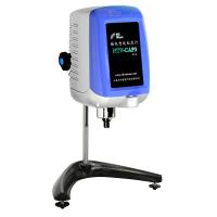
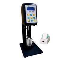
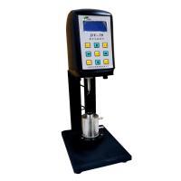
Let's take a look at the accessories of the DV-79 viscometer and what is its overall structure?
Instrument configuration
(1) 1 digital viscometer (2) 1 power adapter (3) rotor (A, B, C, D, 1 each) (4) RTD temperature probe (5) 1 B-type test container (6 ) 1 set of connecting rods at the coaxial end of the motor (7) 1 set of hexagon wrench
Optional configuration parts:
(1) Special printer (2) Constant temperature Water Tank (3) Standard type silicone oil (4) Type A test container (including A, B, C, D rotors)
Specific installation method
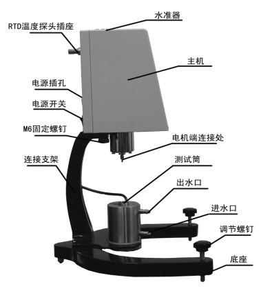
(1) Take out the main engine, the connecting rod at the coaxial end of the motor, the rotor, the base, the base bracket, the container bracket plate, two M6 cylindrical screws, etc. from the packing box, and place them on a stable workbench. Prepare constant temperature external circulating water and control it to the required temperature.
(2) Install the container support plate on the bottom of the base support, use M6 hexagon socket head screws and washers to assemble the base (two holes in the middle on the back of the base) with the container support plate and the base support, and tighten the two holes with the hexagon socket head plate. One M6 hexagon socket head screw.
(3) Put the main unit (front facing forward) on the base support (middle position), connect the main unit and the base support with M6 cylindrical screws through the second hole of the base support, and tighten the M6 cylindrical screws by hand (note: the bottom of the main unit It must be close to the plane of the base bracket).
(4) After the main unit and the base are assembled, adjust the horizontal adjustment screws on the two bases until the level on the top of the viscometer is at the center.
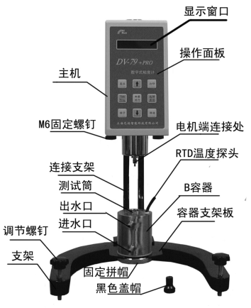
(5) Make sure that the power switch of the viscometer is in the OFF state, and install the RTD temperature probe on the B container to the interface on the back of the digital viscometer. If there is a printer, please install it to the RS232 interface.
(6) Unscrew the fixed joint cap on the B container by about 4mm, embed it on the container support plate (installation diagram), fix the fixed joint cap with a wrench, and initially fix the center position of the B-type container.
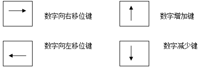
Key Function
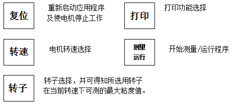
DV-79A, DV-79B have the following function keys


- 1Application of SNB-1 + L0 digital swirl/spin Viscometer in Oil Industry
- 2Glue viscosity test scheme
- 3Significance and method of cement slurry viscosity test
- 4Polymer Solution Viscosity Testing Solutions
- 5How to test the viscosity of lithium battery stirring slurry?
- 6How to Test Sugar Viscosity with a Viscometer
- 7Professional technology teaches you how to choose a digital viscometer?
- 8How to choose a digital rotary viscometer in the laboratory?
- 9GB/T 20623 Emulsion Performance Testing Scheme for Architectural Coatings [Instrument List]


