Paper and board - Determination of tensile strength - constant rate loading method
definition
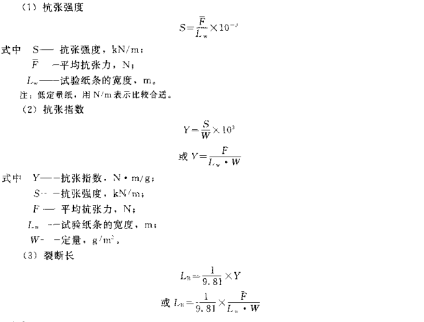
(1) Tensile strength Under the conditions specified in the standard test method, the maximum tensile force that a unit width of paper and cardboard can withstand before it breaks, expressed in N/m or N/15 mm.
(2) Breaking length Assuming that one end of paper and cardboard of any given width is hung up, calculate the maximum length broken by its own weight, expressed in km.
(3) Tensile index Tensile strength (expressed in N/m) divided by quantitative.
(4) Elongation Measure the ratio of the elongated length to the length of the original sample when the paper and cardboard sample is stretched to break under the conditions specified in the standard test method, usually expressed as a percentage.
principle
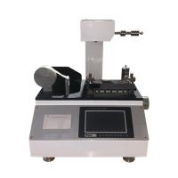
The Tensile Strength Tester measures the tension when stretching the sample of specified size until it breaks under constant speed loading. If necessary, the maximum elongation at break can be recorded at the same time.
instrument
The Tensile Strength Tester can meet the requirements of acting on the sample under the specified constant speed loading to measure the tensile strength and elongation. Tension resistance can be recorded as a function of elongation on a tape Recorder or a similar device. The Tensile Strength Tester shall include the following devices.
①Browsing and recording device. Instruments with an accuracy of ± 1% for tension at break and ± 0.5 mm of reading for elongation were used. The effective measurement range of the Tensile Strength Tester needs to be used between 10% and 90% of the total range.
Note: For the precise determination of the elongation of paper with an elongation of less than 2%. Measuring elongation with a pendulum Tester is not accurate enough. It is recommended to use a Recorder with an electronic amplifier or place a suitable extensometer on the paper strip to accurately measure the actual length. Prevent the sample from sliding and other noises in the clamp.
Adjustment of loading speed, adjust the loading rate so that the sample breaks within (20 ± 5) s.
Note: In order to meet the requirement that the change of loading rate is not more than 5%. Instruments of the pendulum type shall not be operated at a pendulum angle greater than 50°.
③ Fire two samples. The entire width of the specimen should be clamped without slipping and damaging the specimen. The centerline of clamping should be coaxial with the centerline of the sample, and the direction of the clamping force should be perpendicular to the direction of the length of the sample by ±1°. The wife or fire wire of the two clips should be kept parallel and should also be kept on the same plane during the test.
The distance between the two clips is adjustable and should be able to adjust to the required test length. But the error shall not exceed ±1mm,
Instrument Calibration
① Use weights with an accuracy of 0.1% to measure the force of the instrument. The device is also calibrated for use.
②Calculate the applied force produced by the mass of the weight and the acceleration of free fall caused by gravity.
③ Within the range of the force to be measured. Mechanisms that measure elongation with internal vernier calipers or block gauges, etc., should also be calibrated using recording devices.
④ Some Tensile Strength Testers can elongate the measuring force part when loading. In order to ensure that the test results will not be affected, the measuring force and secondary length components should be calibrated at a few points within the H should be measured.
Experiment preparation
① Sampling according to the standard method.
②According to the standard method for temperature and humidity treatment.
③ Sample cutting. According to the needs of the experiment, cut the sample width of 15mm, 25mm or 50mm, the error is -0.1mm and +0.2mm; the length of the sample should be able to clamp the sample without touching the part of the sample between the clips, usually the length is 250 mm. When measuring laboratory hand-written slides, cut as long as possible, and use a clip distance of 100 mm. For some thin pages that are difficult to cut neatly, you can alternately insert harder paper between the second and third layers of tissue paper, and then form a stack with a lining to cut out the experimental paper strips. There are no less than 10 vertical and horizontal lines.
Measurement
① Check the zero position and front and rear levels of the measuring mechanism and recording device.
②Adjust the distance between the upper and lower clamps as needed, and clamp the sample in the clamps to avoid contact with the test area between the clamps. Apply a pretension of about 98mN (10 g) to the sample so that the sample is clamped vertically. Between two clips.
③Do a prediction test first, and find out the loading rate of the sample breaking in (20±5)s.
④ Start the measurement, and record the maximum applied force until the sample breaks, and record the elongation when the bundle breaks if necessary. At least 10 measurements shall be made in each direction of paper and board, and the results of these 10 measurements shall be valid. If it breaks within 10 mm from the clip, it should be excluded.
representation of results
Calculate and express the results obtained in the longitudinal and transverse directions of paper and cardboard respectively. There is no orientation difference in laboratory hand-translated slides.
(4) Elongation
Calculate the average elongation of the specimen at break, expressed in mm, and then calculate the elongation at break as a percentage of the initial specimen length. The result is rounded to one decimal place.