Determination method and experimental procedure of bursting resistance of paper and paperboard
1. Definition
(1) Bursting strength: the maximum pressure that a single-layer paper sheet can withstand evenly distributed perpendicular to the surface of the sample, usually expressed in kPa or kgiicm'.
(2) Bursting index The bursting strength of the paper is divided by the quantification of the paper, usually expressed in kPa m2/g
2. Principle
Use the sample chuck to tightly clamp the periphery of the sample placed on the circular film, the sample and the film are free to protrude, and the liquid is pumped in at a constant rate to make the film protrude until the sample breaks. The burst resistance of the specimen is the maximum value of the applied hydraulic pressure.
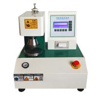
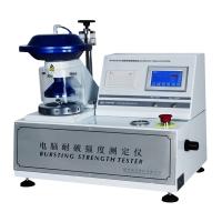
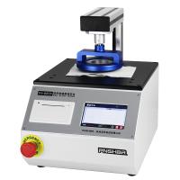
3. Instruments
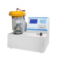
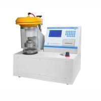
At present, the Mullen (Mullen) type burst Tester is commonly used, which is divided into two types: oil pressure and air pressure. The oil pressure burst Tester uses glycerin (2°Be, 20 ℃) as the pressure transmission medium, and the pneumatic burst Tester uses compressed air as the pressure source to transmit pressure. The structures of paper and cardboard Burst Testers are basically the same, the difference lies in the difference in their technical parameters, and the main differences are listed in Table 8-3.
Its composition includes a pressing mechanism (chuck system), a transmission pressurizing mechanism (hydraulic system), a film and an indicating mechanism.
| parameter | Paper Burst Tester | Cardboard Burst Strength Tester |
| Measuring range kPa (kg/cm²) | 0~600 (0~6); 0~1000 (0~10) | 0~1600 (0~16); 0~4000 (0~40) |
| Pressure ring inner diameter | Upper pressure ring φ30.5mm; lower pressure ring φ33.1mm | Upper pressure ring φ31.5mm; lower pressure ring φ31.5mm |
| Film size | Thickness 0.8~0.9 | The height of the convex part is 2.0~0.2; the diameter is φ27.8 |
| Pressurization speed (ml/min) | 95 | 170 |
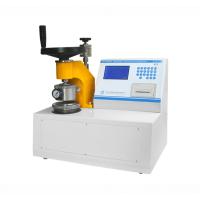
(1) Chuck system
In order to firmly and evenly clamp the sample, the upper and lower chucks are two parallel circular planes, the ring surface is smooth and has grooves. During the test, the inner holes of the upper and lower chucks should be concentric, and the maximum error should not be greater than 0.25 mm. The chuck surfaces should be flat and parallel to each other. During the test, there should be sufficient clamping force to prevent the sample from sliding, but this force should not be so large as to damage the sample, so that it will crack around the sample. Generally, the clamping force should not be lower than 340 kPa (690 kPa for cardboard). Compression lever The old instrument generally uses manual operation, and the new instrument uses compressed air or hydraulic device to automatically compress the sample.
(2) Hydraulic system
The motor drives the worm, worm gear and gear system to move through the belt or coupling, and drives the worm to rotate positively and negatively through the clutch, so that the piston with the leather cup reciprocates in the oil cylinder, thereby pressurizing the sample through the oil medium and pressure relief. The hydraulic system and the liquid used should have no air bubbles, and the pumping volume should be (95±15) mi/min5 for the cardboard Burst Tester (170 ± 15) ml/min].
(3) Adhesive film
The film is round and made of elastic material. The film is firmly clamped, and its upper surface is about 3.5 mm lower than that of the lower chuck (4.7 mm for the cardboard burst Tester). The material and structure of the film should be compatible with the pressure, that is, when the film protrudes above the upper surface of the lower dial: 9 mm, the pressure should be (30±10) kPa (cardboard break-through reading instrument, when the film protrudes When the surface of the lower chuck is 10 mm, the resistance range is 170-220 kPa, and when the protrusion is 18 mm, the resistance range is 250-350 kPa). For a certain protrusion height, usually the new film will protrude higher than the old film. The adhesive film should be checked frequently, and if it is found that the adhesive film does not meet the requirements, it should be replaced when needed. When installing the film, remove any air that may collect under the film.
(4) Pressure gauge
① Bourdon tube pressure gauge. Use within the range of 23% to 75% of the pressure gauge range. It must not be used in the range below 15% and above 85%. The minimum diameter of the dial scale is 95 mm, and the arc of the scale is not less than 270°. The accuracy of any point within the working range should be ± 0.5% of the maximum range. The pressure gauge should have vent holes , and the dial should be divided into at least 70 scales.
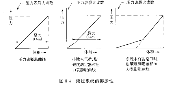
② The expansion of the pressure gauge should be stable within 20% of the entire working range. Even at the maximum range, the liquid to be infused should not exceed 0.4ml.
③The friction torque between the pressure gauge and the pointer is about 0.3 mN m, and the moment of inertia of the pointer is preferably within 1~10 g cm.
④ The operating inertia of the pressure sensor can be ignored. The error of the expansion and pressure Recorder is within 0.2%, and the reading of the digital display device does not change more than: units after the sample ruptures.
4. Instrument Calibration
(1) Calibration of the pressure gauge
For static calibration with piston-type deadweight manometer or mercury column manometer, the manometer should be calibrated at the same position as the burst Tester .
(2) Inertia and friction of the pointer
The moment of inertia at which the pointer indicates the maximum reading can be calculated from the geometry and mass of the pointer. The friction force of the pointer can be measured by installing the pressure gauge vertically, and then fixing a small wire ring of a certain quality on the pointer of the pressure gauge so that it is in a horizontal position. When the pressure gauge is rotated or lightly tapped, the pointer moves slowly and smoothly, and the required torque is 0.2~0.4 mN m (2.04~4.08 g cm), which is determined by the mass of the small metal ring and it to the pointer Axis distances are calculated.
(3) Expansion of the pressure gauge
The expansion of the pressure gauge can be measured with a calibrated plunger or dilatometer. With no air in the system, move the plunger forward for a certain distance and record the pressure produced as indicated on the pressure gauge.
(4) Inspection of the hydraulic system
① Hydraulic system leakage inspection After clamping a hard metal plate between the upper and lower chucks, the hydraulic system is boosted to the highest gauge pressure. The pressure drop should not be greater than 10% within 1 min.
② Check the existence of air in the hydraulic system. Between the sample chucks of the burst Tester, clamp a metal plate with fine lines or pits (diameter 1 mm) on the lower surface. The space under the metal plate is filled with liquid , the expansion of the system is basically consistent with that of the pressure gauge.
Fill the film in the hole of the lower chuck with water and cover it with film. Add a metal plate on the film, drop the upper chuck to clamp it, rotate the transmission shaft by hand, and slowly pressurize until the pressure gauge indicates 98.1 kPa (1kg/cm²), then rotate the transmission shaft to add 0.4 ml (cardboard burst Tester is 1.4 ml) liquid, the pressure indicated on the Leli meter should not be less than 30% of the full-scale reading of the pressure gauge, otherwise there will be more air in the instrument system (Figure 8-4 ).
③The pumping rate of the hydraulic system, fill the film in the hole of the lower chuck with water or ethanol, cover it with a film, cover the film with a metal plate, and drop the upper chuck to clamp it. Hose the house hose to the pressure chamber of the Tester and remove all air from the hydraulic system. Add the pressure test liquid into the straight measuring tube to a certain mark. Rotate the motor shaft by hand to push the movable unit forward, measure the volume of the pumped liquid at different rotation speeds and times, and calculate the pumping rate. It should be within the range of (95±5) ml/min [the cardboard Burst Tester is (170 ± 15) ml/min.
(5) Inspection of sample chuck
Place a piece of carbon paper and a piece of white tissue paper in the middle of the upper and lower central plates, and clamp them with constant clamping force. If the specimen chuck is good, the imprint transferred from the carbon paper to the white paper is uniform and clear, and the entire area clamped by the chuck is well defined. If the upper chuck can be rotated, the chuck print after rotation should coincide with the original print.
The concentricity of the upper and lower chucks can be checked by the following two methods. On a plate with a disc (the diameter of the disc is the same as the inner diameter of the chuck) on the front and back sides, check whether the inner holes of the upper and lower chucks are in line with the two discs respectively. disk alignment. Another method is to sandwich a piece of white tissue paper between two sheets of carbon paper, and check whether the impressions pressed by the upper and lower chucks coincide.
(6) Inspection of clamping force
The burst Tester has a hydraulic or pneumatic clamping device. To adjust the clamping force with a pressure gauge, the pressure gauge needs to be calibrated, and then the value of the clamping force can be accurately obtained according to the contact area between the diameter of the piston and the surface of the chuck.
5. Test preparation
①Take the sample according to the standard method.
②According to the standard method for constant temperature and humidity treatment.
③ Sample cutting. Cut the sample into a size of 70 mm × 70 mm.
④ Shuttle measurement under standard temperature and humidity conditions.
6. Test
① Select the appropriate measurement range first, and use a large-range pressure gauge when forecasting is required.
② Put the sample between the upper and lower chucks, the sample needs to exceed the entire area of the upper chuck, drop the upper chuck, adjust to the required pressure, start the instrument to increase the pressure at an appropriate rate, until the sample ruptures . Return the piston until the rubber film is lower than the surface of the lower chuck, and read the pressure value of the pressure gauge (or digital display).
③ Lift the upper chuck and return the reading to zero for the next test. ·
④ If it is found that the sample slips or is abnormally broken due to crushing, the reading should be discarded. If the reading is lower than 70 kPa (0.71 kg/cm2), it can be tested with multi-layer paper, so that the reading exceeds 70 kPa (0.71 kg/cm2), that is, the measurement result is divided by the number of layers. After determining the number of layers of paper sheets to be used, the samples cut uniformly along the banner of the paper, and 10 samples on the front and back sides are attached to the film for measurement.
7. Calculation of test results
① The average bursting strength P, in kPa, is calculated according to the following formula:
P=B/n
In the formula, B——measured average bursting strength value, kPa
n - the number of layers of the test sample
②Burst resistance index X, kPa m²/g, calculated according to the following formula:
X=P/W
In the formula, P - average bursting strength, kPa;
w——quantitative quantity of the sample, g/m².
Bursting strength and bursting index take three significant figures.


- 1Test method for bursting resistance of paper and paperboard
- 2How to calculate the rupture coefficient of paper and corrugated board?
- 3Why is the blasting factor important in the packaging industry?
- 4How does the rupture strength Tester check the quality of paper?
- 59 Corrugated Box Test Methods to Ensure Packaging Quality
- 6Analysis of common performance definitions for paper inspection
- 7Method for determination of bursting resistance and folding resistance of paper
- 8What are the paper mechanical performance testing instruments? How to maintain

