Paper and board printing - Determination of surface strength - pendulum or spring acceleration method
1 definition
(1) nap
During the printing process, when the outward pulling force of the ink acting on the surface of the paper or cardboard is greater than the cohesive force of the surface of the paper or cardboard, the peeling of the surface is caused. For uncoated paper or paperboard, this delamination generally takes the form of surface fluffing or tearing. For coated paper or cardboard, it is mainly due to powder falling off the surface or blistering and delamination or even tearing of the paper layer.
(2) The printing surface strength is the printing speed at which the paper surface is printed at a continuously increasing speed until the paper surface begins to be roughened, expressed in m/s.
2 principle
Use standard napping oil to print paper strips at a continuously increasing speed under constant pressure, and evaluate the strength of the printed wheat surface of the paper at the minimum printing speed when the napping begins to occur on the paper surface. The higher the speed, the better the strength before printing.
3 Instruments and materials
3.1 Instrument structure
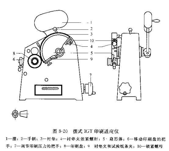
As shown in Figure 8.20, the instrument is a small Tester that imitates the work of a printing machine. Its main body includes two parts, namely: an ink distributIon Meter and a printing Tester.
(1) Ink distributIon Meter
Ink pipette: 2 ml, graduated 0.01 ml.
Polyurethane resin wheel: diameter 60 mm, length 141 mrn.
Active chrome mixer: diameter 94 mm, length 144 mm, speed 50 r/min. Driven chrome roller: diameter 107 mm, length 155 mm.
Small distribution drive series: diameter 48 mm. Length 35 mm. Ink tray: 10 mm wide, 65 mm in diameter, 4 pieces.
(2) printing Tester
Printed fan-shaped body: width 22 mm, radius 85 mm.
Pendulum: elevation angle 165°, swing speed 0~116 cm/s.
Spring accelerator: A speed 0~250 cm/s; B speed 0~300 cm/s; C speed 0~350 cm/s.
Printing pressure device: 0~750 N or 0~-75 kg.
3.2 Other materials
①Standard liner. Thickness (1.5 ± 0.1) mm. There are two kinds of paper pads and rubber pads. Paper pads are used for letterpress samples and rubber pads are used for offset and gravure samples.
②Standard brushing oil. Low and medium viscosity pull-hair oil.
③Standard nap observation light. The incident angle of the light source is 75°, and the observation angle of the observation hole is 30".
④ Diagram of the relationship between printing speed and paper strip printing position, so as to find out the printing speed of each point in the printing area.
⑤ Petroleum ether or solvent gasoline, petri dishes, soft brushes, and soft gauze that does not shed hair, used to clean the brushing oil.
4 Preparation before the experiment
①Sampling according to the standard method.
② Carry out temperature and humidity treatment according to the standard method.
③ Sample cutting. Cut (250-270) mm × 22 mm samples from the sample, no less than 5 pieces on the front and back of the sample, and the length direction is the longitudinal direction of the sample. Mark the front and back separately.
④ Fixing and tensioning of the gasket. Rotate the fan-shaped body so that the clip 9 is located at the position corresponding to the handle 2, place the pad 3 flatly on the fan-shaped body, clamp the front end with the clip, insert the other end of the pad (the upper two layers of the paper pad) to tension Axis 4 places. The rotating sector is at the printing starting position. And at the same time lay the pad flat. Loosen the lock nut 10 of the tensioning shaft, and rotate the knurled screw of the shaft clockwise. Tighten the liner (upper two layers of the paper pad) and hold the screw until the jam nut 10 is locked. If the liner is damaged, it needs to be replaced in time.
⑤ Adjustment of printing pressure. base on needs. Select the speed of the spring accelerator (A, M, B): clamp the test paper strip on the quadrant so that it is flat on the pad. Turn the handle 6 clockwise to the end, and insert an uninked printing disc on the shaft. Turn the fan-shaped body to the starting position, and turn the handle 6 counterclockwise to the end. Rotate the handle 7 as required to adjust the pressure of India, so that the reading is 215N or 343.Nv (190N).
5 test steps
① Test conditions. All tests should be carried out under standard atmospheric conditions, and it is necessary to ensure that the instruments and test equipment are in equilibrium with j standard temperature conditions. In order to achieve higher test accuracy. The temperature conditions in the laboratory should be better controlled within the range of (23-0.5) °C.
② Install the sample. Clamp the sample on the clamp, and make sure that the paper strip is parallel to the liner, and turn the sector to the starting position.
③Preparation of printing plate. First, draw the standard napping oil into the ink filling tube. Be careful not to inhale air. If you find that the brush oil gushes out by itself after using the ink injection tube to inject the brush oil, it means that air is mixed in the ink injection tube. All brushing oil in the ink injection tube should be removed. Then re-inject.
Before the test, use a soft brush dipped in petroleum ether or solvent gasoline to scrub the ink distribution roller and printing plate on the ink distributIon Meter, and use a toilet paper or soft cloth to dip petroleum ether or solvent gasoline to scrub the metal roller on the ink distributIon Meter.
Use the ink injection tube to apply 1 ml of nap oil evenly to the front cylinder along the axis of the ink distributIon Meter cylinder. After the uniform circle is at least 8 rmin, put the two printing plates on the polyurethane resin roller of the ink distributIon Meter at the same time for inking, and the inking time is (90+3) s.
④ Printing samples. Insert the inked printing plate onto the shaft of the printing machine until it snaps into place. Turn the handle 6 counterclockwise to make the printing disc contact with the sample. Pull the handle 2 to complete a printing.
⑤ Judgment of napping. Mark the center of the initial (stationary) contact surface of the strip print as the starting point of the print (the middle of the dark print with a width of about 5 mm at the end). Observation holes to observe the napping situation. The paper surface begins to be continuously fluffed in pieces as the starting point of the napping, and marks are made, and then the printed surface strength of the sample is found in the speed-pressure curve table. For the foaming and delamination of the cardboard, it can be Observe by bending the print with the printed side in. Record the value measured and the type of fuzzing.
Note: If the printing speed used does not fluff the sample. It is necessary to switch to high-speed printing. If the highest speed still cannot fluff the sample, use high-viscosity brushing oil, and then test from low speed to high speed. If the viscosity of the napping oil used is within 20 mm and the fluffing begins, it is necessary to switch to a low-viscosity napping oil, or reduce the printing speed for testing.
⑥ After each sample is printed, wipe the printing disc with toilet paper or soft cloth dipped in petroleum ether or solvent gasoline, and continue printing after drying. After every 10 prints, add 0.16ml brushing oil evenly along the axis of the roller on the inking machine with the ink tube, and continue to ink the printing plate after the distribution is even, and the distribution time of additional ink: before the 1970s No less than 3 minutes; ink printers after the 1970s no less than 45s.
All 50 samples to be tested should be cleaned. Re-oil the brush and test again.
Print at least 5 samples on both sides (one-sided printing paper only measures the printing side). After finishing the test, wipe the printing plate and ink printer clean.
6 Calculation of results
The surface strength of the sample is reported as the arithmetic mean value of the positive and negative sides in the longitudinal direction, and the maximum and minimum values are reported, expressed in m/s.
The calculation result takes three significant figures.
The report should indicate ink viscosity, printing pressure, instrument model and printing speed range.