Principles and methods of Bendtsen breathability meter test method
(1) Bendtsen air permeability meter
①Structure and working principle
Except that the air permeability test head is different from the Bendtsen roughness meter, the rest of the structure and main technical parameters are the same as the Bendtsen roughness meter. The air permeability measuring head is a component that clamps the sample between the annular plate and the circular rubber gasket. The circular gasket must ensure that the test area of the sample is (10±0.2) cm2 after the sample is clamped. The inner diameter of the large measuring head is 35.68±0.05)mm and the area is 10cm2, while the inner diameter of the small measuring head is (25.23±0.05)mm and the area is 5cm2. The working principle of the Bendtsen air permeability meter is: the sample is placed between the rubber pad and the upper pressure ring and clamped, the air flow is generated by the Air Compressor, and enters the air permeability measuring head through the buffer bottle, the pressure regulator valve, and the flow meter. Because there is a pressure difference between the two sides of the sample, a small amount of air flows through it, and the flow meter displays the reading, that is, the air permeability of the sample.
② Calibration procedure
a. Air tightness check.
b. Calibrate the flowmeter with a capillary. Install the capillary calibrator on the joint for measuring air permeability, and put the instrument in the working state of measuring air permeability. When the compressed air enters, the float of the flowmeter rises and stabilizes to a certain value. At this time, the value on the scale is indicated by the top of the float, which should be basically consistent with the value marked on the capillary calibrator, and the error should not exceed 3%.
(2) Test method
①Sample collection and processing. Sampling according to GB450, cut 10 pieces of 80mm×80mm samples along the transverse direction of the paper web, and mark the front and back sides. According to the requirements of GB10739, carry out temperature and humidity pretreatment on the samples.
②Adjust the instrument level.
③ Start the compressor to ensure that there is no vibration that causes reading errors.
④Select a suitable gas rotameter so that the reading is at 80% of the scale.
⑤Adjust the valve on the base so that the air flow passes through the selected gas rotameter. After the airflow begins to enter, gently place a 1.47kPa stabilizing weight on the shaft and make it rotate continuously, slowly and smoothly. Remove it before the air flow stops.
⑥Adjust the outlet valve of the flowmeter to increase the exhaust volume, and use a pipe with a length of less than 20mm to connect the measuring head and the outlet valve. If the pipe is too long, it will cause pressure fluctuations between the flowmeter and the measuring head.
⑦ Place the sample between the annular plate and the gasket, and after clamping for 5s, record the reading of the flowmeter.
⑧After the test for a certain period of time, the flow meter and sealing performance should be checked at any time.
⑨Test the rest of the samples with the above method. After the test is over, remove the voltage stabilizing weight and turn off the compressor. The test results are expressed as the arithmetic mean of all test results (including positive and negative sides).
-
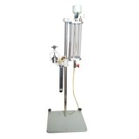
![Yongxin ZQX-1000 paper Porosity Tester Schopper method]()
-
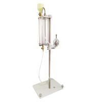
![JINGWEN JW123 paper Air permeability meter]()
-
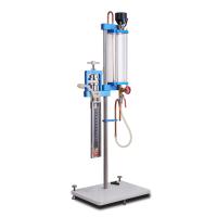
![YINUO YN-TQD01 Schauber Air Permeability Tester]()
-
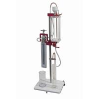
![CHINA BLD-TQ20 paper Porosity Meter]() CHINA BLD-TQ20 paper Porosity Meter$ 1117.00
CHINA BLD-TQ20 paper Porosity Meter$ 1117.00 -
![PUYUN PY-H614 paper Porosity Tester Schopper type]()
-
![YINUO YN-TQD03 Battery Separator Porosity Meter Gurley Bentsen Method]()
-
![YINUO YN-TQD02 Electronic Porosity Tester]()
-
![PNSHAR PN-ZQX1000 paper Porosity Tester]()
-
![YANTE YT-TQD1000 paper Porosity Tester]() YANTE YT-TQD1000 paper Porosity Tester$ 1100.00
YANTE YT-TQD1000 paper Porosity Tester$ 1100.00


- 1Porosity Tester verification & maintenance
- 2Application of Porosity Tester in Thermal Paper
- 3How to use the differential pressure method to test air permeability?
- 4How to test air permeability with a non-porous paper air permeability meter?
- 5What is the measurement principle of microporous paper breathability meter?
- 6Principles and Methods of Gurley Air Permeability Meter Test Method
- 7Principle and method of Schopper air permeability meter test method
- 8What are the common physical properties of paper?
- 9Common tests for corrugated box production
-
![Yunda YD-TQD-A Paper Air Permeance Tester 0~2500mL/min]()
-
![CHINA BLD-TQ20 paper Porosity Meter]() CHINA BLD-TQ20 paper Porosity Meter$ 1117.00
CHINA BLD-TQ20 paper Porosity Meter$ 1117.00
