Principle and design of shunt pipe for coating hanger mold
The main purpose of the die is to define the width and provide a uniform coating in terms of cross-sectional thickness and smoothness. The manifold and hanger sections of the mold are the main components to achieve even distribution. Smoothing will be discussed in a later section. There are two basic styles of manifold designs in use today: the coat-hanger type, with a volume-reducing cross-section (Fig. 20.1), and the T-type, with a constant cross-section (Fig. 20.2).
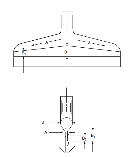
Figure 20.1 Decreasing volume manifold for hanger.
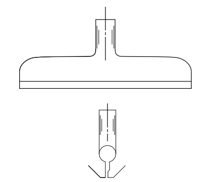
Figure 20.2 Constant cross-section manifold.
Either way, the flow through a manifold is similar to that through a pipe in that the resistance to material flow increases as the length increases. The wider the die (and the longer the pipe), the greater the resistance to flow. Therefore, the main criterion for a good mold design is to ensure adequate flow at both ends of the mold as width requirements increase.
The coat hanger mold uses a different length slot section (lead zone) downstream of the manifold to compensate for this pressure increase (see area B, Figure 20.1). The pressure drop in the foreland section needs to decrease at the same rate as the pressure drop in the manifold section increases. If the sum of these two components is equal at any point throughout the flow, the result is a uniform flow.
It can be seen that while the general coat hanger design is fixed, the overall dimensions can vary considerably depending on the requirements for a given die width, flow rate or general coating material. Generally speaking, as the mold becomes wider, the length of the leading section (B,) needs to be longer, and the manifold becomes larger; as the flow rate increases, the manifold needs to be larger, and the gap height at B also needs to be larger. Compensating for the manifold downstream of the foreland section makes a wide variation in die design.
These large internals are designed for applications characterized by coating materials with widely varying viscosity levels or where extreme flow rate ranges are required. Larger flow channels are less sensitive to velocity and viscosity changes than small channels. Small internal design for materials that require a short residence time in the mold due to thermal degradation or high shear rates to prevent gelation (thixotropic materials).
In analyzing the hanger manifold, it is important to emphasize that the cross-section of the manifold decreases as it approaches the end of the mold (dimension A in Figure 20.1); this rate of decrease can also be varied to suit a particular application. Since material flows out of the front of the mold along its entire width, less material is present on the manifold as it nears the end of the mold. The reduction in manifold volume is to maintain the velocity of the material at the end of the die at a maximum to compensate for the lower flow rate and to prevent carbonization of the resin or thixotropy or viscosity changes of the expanding adhesive.
In conclusion, it can be seen that the hanger manifold design can be modified to suit the application and still achieve the primary criterion of uniform flow distribution. In order to adequately design a hanger mold, the following information is required:
1. Rheology Curve (see Figure 20.3) – The rheology curve, the fingerprint of a particular resin, predicts its viscosity level at a given shear rate; this is required for all non-Newtonian or shear-thinning fluids
2. Flow or rate range
3. Material density at processing temperature
4. General material properties, such as thermal degradation or thixotropy
A t-manifold of constant section style (see Figure 20.2) has no compensating front section; this is because of its inherent design. Instead, this die design relies on a larger manifold cross-section to reduce resistance to flow towards the end of the die; larger manifolds provide less resistance and better flow distribution. In theory, it is impossible to have an even distribution, because no matter how large the manifold is, there is always some pressure drop across it, and therefore, less flow is going to the ends of the die than to the center.
Larger manifolds have some disadvantages, the residence time is greatly increased and the flow is almost stagnant at the end of the die. The overall internal flow channel design cannot be increased or decreased according to the specific application, because it is limited by the size of the flow channel to achieve a certain flow distribution.
Thickness variations can sometimes occur if the flow presented to the die is not constant over time, if the fluid is not uniform in temperature and mixing, and due to inherent errors in viscosity measurements and theoretical flow calculations.
To adequately adjust for these flow changes, a flexible lip is required as a fine-tuning adjustment. Setting multiple inlets or a pump in the mold is just for uniform distribution, minimizing the effect of lateral pressure drop and simplifying the work of manifold design.
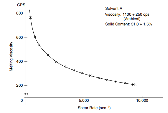
Figure 20.3 Rheological curves.
While the multi-inlet design attempts to minimize flow distribution problems, it actually complicates it by introducing two pressure drops for each installed inlet. This can lead to steps in coating thickness and, when using high viscosity fluids, parting lines or "zippers" in the coating.
In-mold pumping devices can improve flow distribution in simple T-slot manifold dies; however, they also have some inherent disadvantages. Due to its complex design, streamlined flow and self-cleaning features are compromised. Since the gear pump is built into the mold, the high shear will cause some of the adhesive to break down. The real question is, why make the tool more complicated than necessary?

- 1Application of Slot die coaters in Lithium Battery Coating
- 2Installation of the material head of the slit coater [including video demonstration]
- 3Operation demonstration of slit coating machine [including video explanation]
- 4How to clean the coating mold?
- 5How to realize the automatic control of slit coating
- 6Points to pay attention to in the design of support rollers for slit coating
- 7Principle and method of mold positioning for slit coating
- 8How to design lip for slit coating?