Principle and method of mold positioning for slit coating
Groove head-to-roll position and contact angle
1. In the past, the contact position at 12 o'clock (Figure 20.9B) or 6 o'clock was commonly used. We find that the 4 or 5 o'clock point of contact is advantageous in most situations today (see Figure 20.9A).
This is due to improved operator accessibility and the elimination of running water after the pump is shut off.
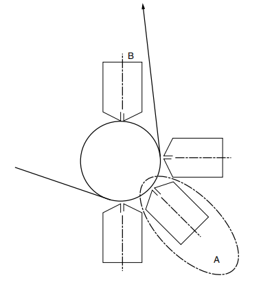
Figure 20.9 Die location.
2. Contact angle depends on lip profile, gap between die and roll, roll hardness, roll diameter, lip step difference, lip profile and material spreading tendency. It is impossible to predict this angle without all these factors and in-depth experience.
3. Reduced contact pressure is necessary to reduce roll and lip damage.
4. Since roll deflection is difficult and costly to eliminate, if a roll deflection problem occurs, a die that can deflect or bend to accommodate roll deflection is required. Steel rolls are often used to support the elastomeric roll to reduce deflection problems, and a heated adhesive is used to help cool the elastomeric roll.
5. The angle of attack of the die against the roll needs to be rotated about the pivot point shown in Figure 20.8 to obtain the best and most reproducible coating surface.
lip contour
The importance of the lip shape and the relative position between the front and rear wipers in today's coating technology cannot be overemphasized.
In some cases, with today's high-tech coatings, an even and proper level of wiping action is required to produce a satisfactory coating. Due to the shear thinning properties of today's harder adhesives, proper profile and angle of attack will produce a smooth, uniform coating. Any variation in the contour of the lips will result in different swipes, resulting in an uneven look. Since, with modern application heads, even distribution is not a function of the lip, we can limit the lip to a single function - namely creating the proper environment when laying.
There is no hard data on lip design due to the interrelationships between roll diameter, roll hardness, line speed, substrate, lip design and adhesive viscosity characteristics that come into play. There seem to be two technology camps. One set adheres to a flat, fixed wiper lip with a distinct step between the feed lip and the wiper or discharge lip. Another group tended to use rotating or fixed poles on the mopping area. This rod design is as old as mold coating and has been patented several times.
Die Holder Design and Operation
The chip and mount interrelationship requires both units to be equally important as one. The items in the series of design specifications shown in Figure 20.10 are absolutely essential to the successful operation of the slot coater head and are explained in Section 20.10.4.
Application and utilization of existing equipment designs will determine better die-to-roll placement. Operator convenience and the ability to see the placement point are very important. We consider installation position A in Figure 20.9 to be very favorable, while position B is very unfavorable.
The support bed needs to be completely rigid and vibration-free. Any sagging or bowing in the die can create problems in aligning the die with the roll. Therefore, we do not recommend supporting the mold from the end. On heated molds, designers also need to allow thermal growth while maintaining mold straightness.
Support and Adjustment System Design Specifications
Item 1 in Figure 20.10: The mold should be supported on a precision lapping pad and curl warpage corrected with mold straightness (profile) adjustments. On heated molds, insulation should be provided between mold frames and allowances should be made for mold growth.
Item 2 in Figure 20.10: A heavy-duty rectangular tubing crossbar should be used to maintain straightness during operation and adjustments.
Item 3 in Figure 20.10: "X" in/out adjustment using machine tool rails, using quick pneumatic and hydraulic soft stop cushions. Micro-stop correction adjustments with dial gauges or LVDTs shall be provided for each end.
Item 4 in Figure 20.10: This 'Y' adjustment is used for scroll axis position alignment.
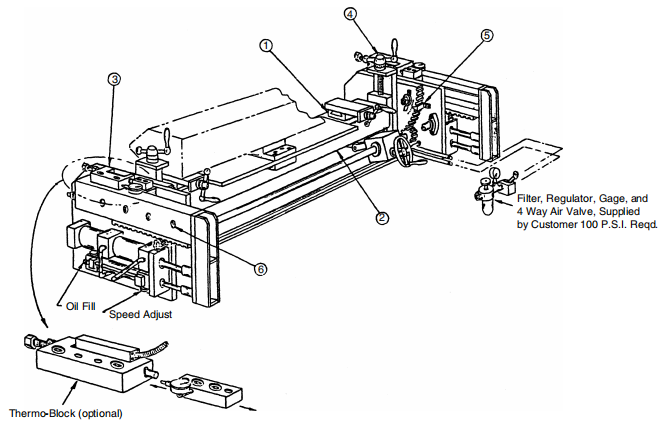
Figure 20.10 Coating mold support
Item 5 in Figure 20.10: This is the angle of attack positioning adjusted by the rack and pinion arrangement, with indicator marks in degrees. Note that the angle of attack movement is centered on the lip (coating contact) point.
Die-to-roll positioning
Flexibility and repeatability are the main requirements. Difficult adhesives, speeds and substrates will require different setup positions and the ability to easily change die to web position with accurate repeatability cannot be overemphasized. The support frame is required to allow for in-and-out movement and angle-of-attack adjustment (see Figure 20.10).
The in/out adjustment has two functions: (a) rapid travel of 5 to 8 inches (130 to 200 mm) to allow lip cleaning; (b) micro in/out to fine-tune the roll-to-batch gap distance. This adjustment should allow for different end-to-end clearances.
The in/out adjustment needs to be in a straight line, always moving directly on the centerline of the roll. (Pivot mounts are not recommended.)
Angle of attack position adjustment
In order to create different shear levels for proper film formation at different speeds, the angle of attack needs to be adjustable. This movement should be precise and smooth, and the range of motion should be around ±5°.
IMPORTANT: When adjusting one anchor point, the other roll-to-mold relationships remain the same. Angle of attack adjustment requires rotation around the point shown in Figure 20.8.
lip opening setting
Depending on material and layup, a uniform lip opening gap of 0.008 to 0.012 inches should be established prior to start-up (Figure 20.11) and adjusted for proper flow and layup after start-up.
The lip opening setting adjusts the coating weight thickness, not the gap between the die and the roll. Roller coaters can struggle with this because they have traditionally used the roll-to-roll gap as a coat weight adjustment.
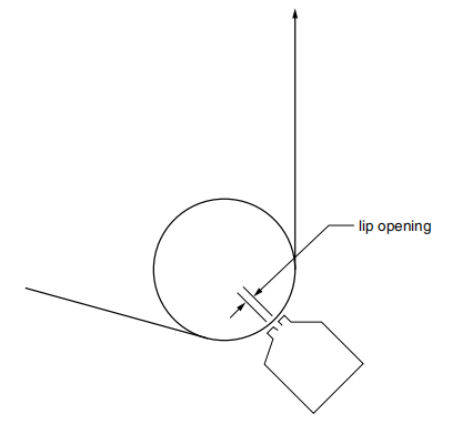
Figure 20.11 Lip opening setting
Die-to-roll gap setting
Typically, the distance from the die to the roll or substrate is determined by the thickness of the web and the viscosity of the fluid to be applied. The more clearance that can be maintained, the less damage can be caused by positioning or starting errors.
As a rule of thumb, we recommend a gap equal to the thickness of the substrate between the substrate and the feed lip. This distance may be less for very low viscosity materials or materials that are difficult to smooth. Make sure the clearance is from the web to the lip, as shown previously (Figure 20.6), and not from the roll to the lip.


- 1Application of Slot die coaters in Lithium Battery Coating
- 2Installation of the material head of the slit coater [including video demonstration]
- 3Operation demonstration of slit coating machine [including video explanation]
- 4How to clean the coating mold?
- 5How to realize the automatic control of slit coating
- 6Points to pay attention to in the design of support rollers for slit coating
- 7How to design lip for slit coating?
- 8Principle and design of shunt pipe for coating hanger mold