Introduction of various functions of steel bar scanner and practical operation of measurement [video demonstration]
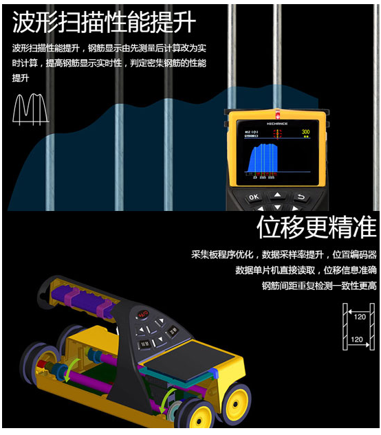
Rebar scanners are often used to test the position of steel bars inside concrete structures, the thickness of protective layers, the diameter of steel bars and the spacing of steel bars. The steel bar scanner can not only quickly provide high-precision detection data, but also accurately draw the distribution map of the overall steel bar. It also meets the requirements of GB 50204-2015, JGJ/T152-2008, DB11/T365-2006 and other standards, and has the characteristics of faster speed, higher precision and stronger resolution.
Function introduction
After the instrument is turned on, there are four plates: measurement plate, data plate, system plate, and closing instrument plate on the screen.
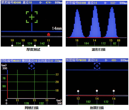
The measurement sections include: thickness detection, waveform detection, mesh detection, section detection, and instrument calibration.
The data section includes: data browsing, data uploading.
The system section includes: setting the automatic shutdown time and instrument number.
实验操作
After booting, click the measurement section, enter the instrument calibration, and click "OK" to complete the calibration. (Note: After the calibration is completed, the sensor at the bottom of the instrument needs to be far away from the metal object). During mesh detection, the X-axis and Y-axis can be switched through the panel button, which does not affect the test data.
| Experimental steel bar diameter | Instrument error | Thickness detection | experimental interval | Waveform detection | X/Y axis mesh inspection | Profile detection |
| 16mm | 1mm | 21mm、31mm、41mm | 148mm | 21mm、31mm、41mm | 21mm、31mm、41mm | 21mm、31mm、41mm |