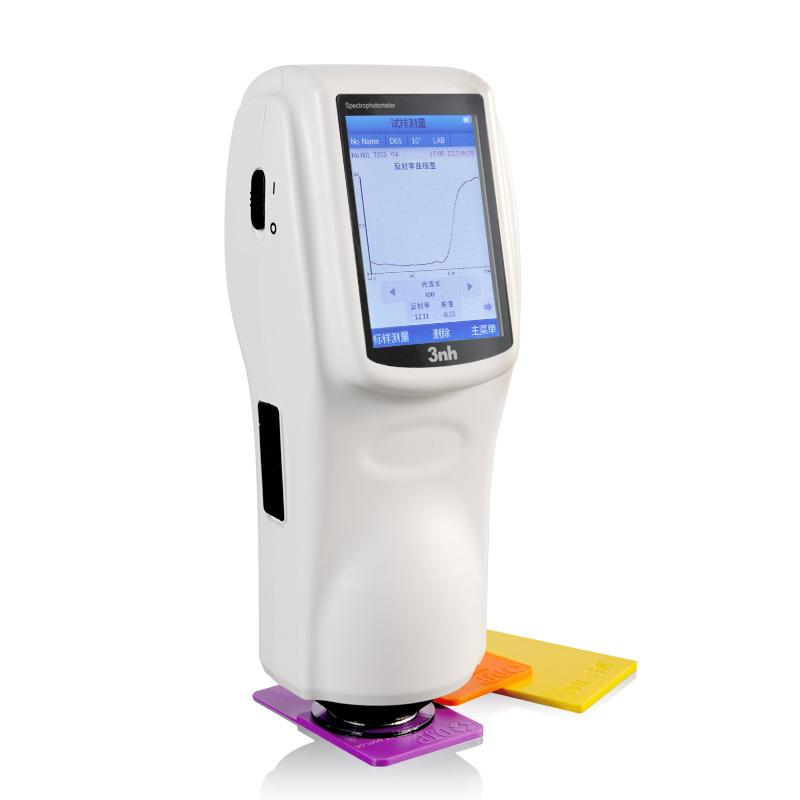
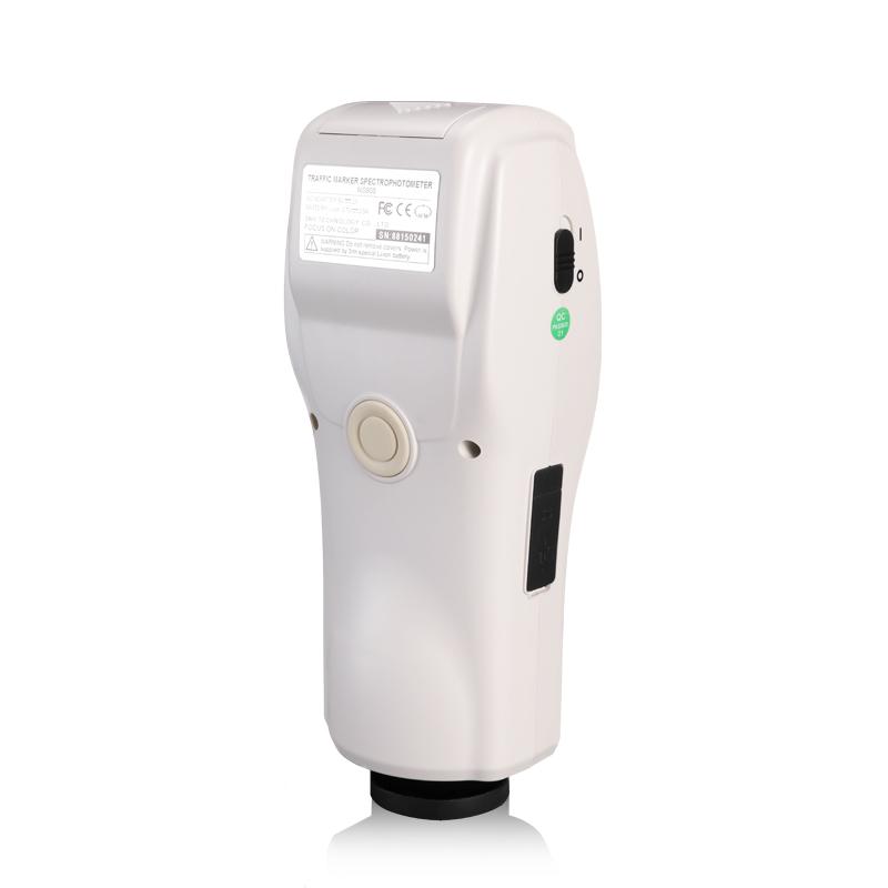
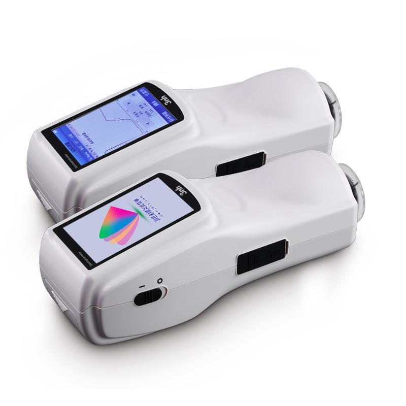
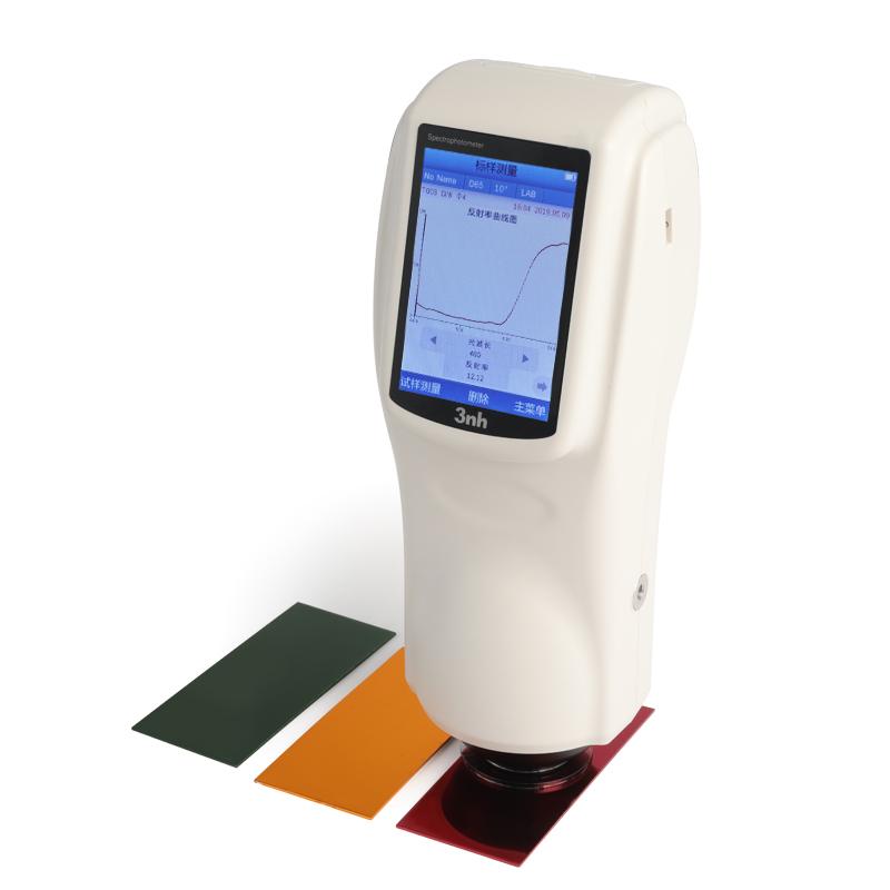

3NH NS808 traffic sign measurement module Colorimeter
SE NS808
NS808

3NH NS808 Traffic sign measurement module ColoriMeterSPEC
3NH NS808 Traffic sign measurement module ColoriMeterDetails
3NH NS808 Traffic sign measurement module ColoriMeterPacking list
- SKU
- NB012060
- Lighting method
- 45/0 (45 ring uniform illumination 0 ° reception);
- Sensors
- Silicon photodiode
- Reflectance Measurement Range
- 0~200%
- Lighting source
- Combined LED Light source
- Measurement time
- 1.5s
- Measurement caliber
- Φ8mm
- Spectroscopic reflectance Repeatability
- Standard deviation within 0.1% (400~700nm: within 0.2%)
- Operating language
- Chinese, English
- Interface
- USB/TTL printing serial port
- Viewing Angle
- CIE 2°/10°
- Available Light Sources
- D65,A,C,D50,D55,D75,F2,F6,F7,F8,F10,F11,F12
- Color difference formula
- ΔE*ab,ΔE*uv,ΔE*94,ΔE*cmc(2:1),ΔE*cmc(1:1),ΔE*00
- data storage
- 1000 master standards and 10000 samples
- Power supply Voltage
- Lithium battery, 5000 cycles in 8 hours
- display mode
- Light spectrum graphs/data, sample chromatic values, color difference values/graphs, pass/fail results, Color bias, Color simulation
- Operating environment
- 0~40℃(32~104°F)
- Storage environment
- -20~50℃
- Dimensions
- 90*77*230mm
- Weight
- Approx. 600g
- Inter-instrument Agreement
- ΔE*ab<0.2
- Display
- TFT true color 3.5inch, capacitive touch screen
- Wavelength range
- 400~700nm
- wavelength interval
- 10nm
- Chroma indicator
- WI, YI, homochromatic index MI, colour fastness, discoloration fastness, force, coverage
- Color Space
- CIE LAB,XYZ,Yxy,LCh,CIE LUV
- Repeatability of chromatic value
- Delta E * ab within 0.04

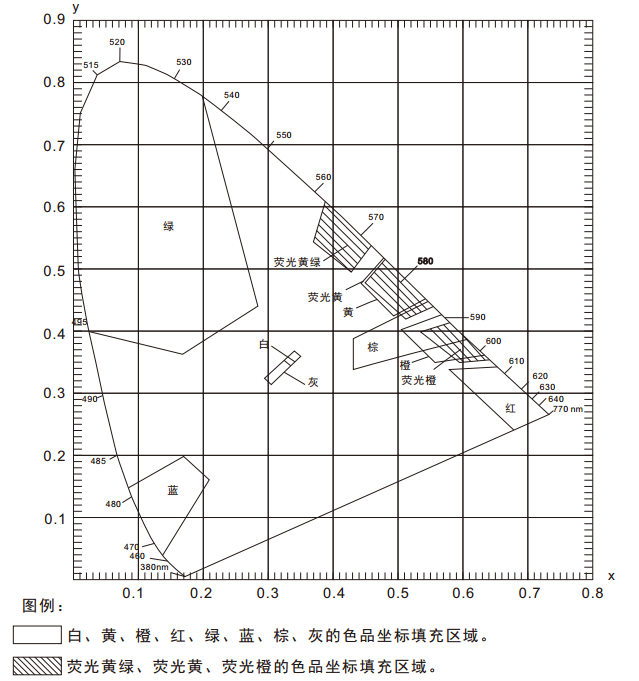
In the "GB 2893 Safety Color", "GB/T 18833 Road Traffic Reflective Film" and other related standards, a color area (multiple color coordinate points) and brightness factor requirements are usually given, and under the conditions of D65/A light source and 45/0 geometry, determine whether the sample falls in the corresponding color area, so as to determine whether the sample meets the color requirements specified in the standard. Since the color area is polygonal, as shown in the figure below, it is not possible to make a judgment with a conventional Spectrophotometer . The NS808 Colorimeter can easily solve this problem with the traffic sign measurement module of SQCT software.
1. Menu introduction and test preparation
NS808 traffic road sign special Spectrophotometer built-in D65 / A / C / F2 and other light sources, geometric optical path structure of 45 / 0 (45 ° annular uniform illumination 0 ° reception), the instrument can be convenient to test a variety of reflective film luminance factor, color coordinates, CI E L * a*b and other chromaticity data; It has a wide range of applications in the laboratory field.
1.1 Menu Introduction
The traffic sign test module of NS808 is mainly realized by the host computer software SQCT with NS808 instrument. Before use, you need to install the SQCT host computer software, and then connect the NS808 instrument, and then open the host computer software, the default is the ordinary test interface, as shown in Figure 1, under the interface, you can complete the test of CIE L*a*b, XYZ, ΔE*ab, ΔE*cmc, ΔE*00 and other chromaticity data, please refer to the introduction of the detailed menu and toolbar, please refer to the software comes with the "color management control software manual", here focuses on the traffic sign test module.
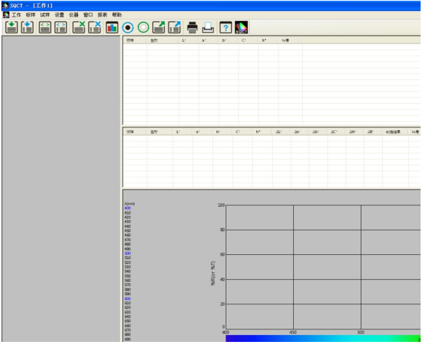
Figure 1
Click "Settings - >Traffic Landmark Measurement" to enter the traffic landmark test module, as shown in Figure 2. Click "standard", as shown in Figure 3 and 4, there are "add standard", "modify standard", "delete standard", "road traffic reflective film GB/T 18833", "safety color GB2893" and "custom" submenus under the menu, and these submenus are introduced in detail here.

Figure 2
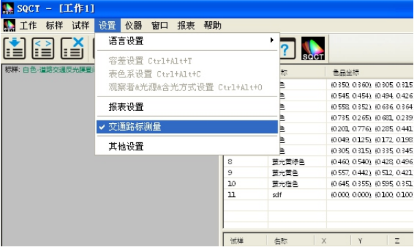
Figure 3
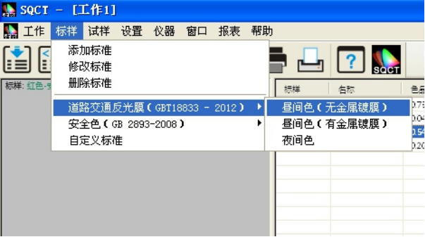
Figure 4
(1) Add standards
In the traffic sign test, the standard is usually a color area, which we call the "polygon-tolerance standard", that is, the color coordinates of each vertex (at least 3 points) in the color area are entered clockwise or counterclockwise, and the software connects the vertices according to the input order to form a polygon-tolerance standard.
As shown in Figure 5, enter the name of the standard sample at position 1, select the light source type (D65 by default) at position 2, select the observer angle at position 3 (2 degrees by default), and enter the luminance factor at position 4 (except for fluorescent substances, the luminance factor of ordinary reflective samples is greater than 0 and less than 1, that is, 0<β). <1). Enter the color coordinate point at position 5, and then click the "Add Vertices" button, then the newly entered color coordinate point will appear in the standard color gamut box, repeat the above steps, enter each color coordinate point in turn, for the color coordinate point that is entered incorrectly, first select it in the standard color gamut box, and then click the "Delete Vertices" button, then delete the vertex. After all the inputs are completed, click the "Add" button at position 8 to complete the establishment of "Polygon-Tolerance Standard".
As shown in Figures 5 and 6, an "ABCD" polygon-tolerance standard named "green" is created.
Note: When entering the coordinate vertices of each color, be sure to enter them in the clockwise or counterclockwise order of the color area graph.
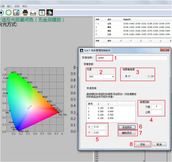
Figure 5
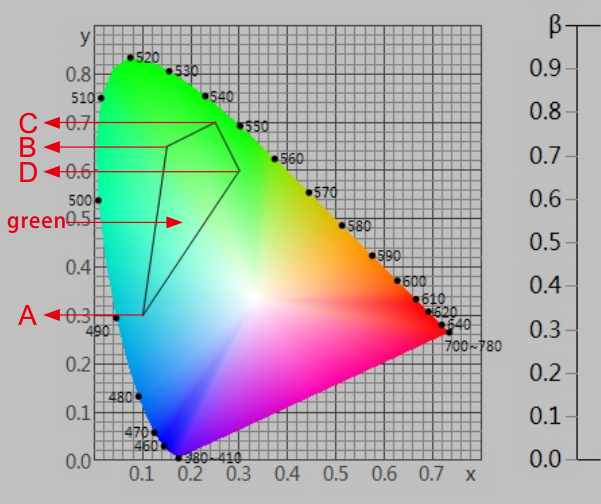
Figure 6
(2) Revise the standard
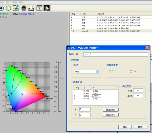
As shown in Figure 7, modify the polygon-tolerance standard with the name "green" established above, select the standard first, and then you can modify the "standard name", "light source", "standard observer angle", "luminance factor", "color coordinates", after the modification is completed, click the "OK" button, then the modification takes effect.
(3) Delete the standard
Select one or more standards in the standard area, and then click "Delete Standard" to delete the selected winning standard.
(4) Road traffic reflective film GB/T 18833
For the standard GB/T 18833, which is widely used in domestic (CN) traffic road signs, the SQCT software incorporates the standard color gamut in the standard, and customers only need to choose according to their own needs.
Assuming that we need the orange (daytime color) in the non-metallic coating type in the standard GB/T 18833 as the polygon-tolerance standard (corresponding to the sixth line of Table 8 in the standard GB/T 18833), we only need to click "standard-> road traffic reflective film GB/T 18833->daytime color" in turn, as shown in Figures 8 and 9, the S1 area shows the corresponding color coordinate points of orange, and the S2 area shows the corresponding polygon-tolerance standard.
On the basis of "Road Traffic Reflective Film GB/T 18833", we can also choose a series of operations such as "Add Standard", "Modify Standard", "Delete Standard", etc., to change "Road Traffic Reflective Film GB/T 18833" to the polygon-tolerance standard we need.
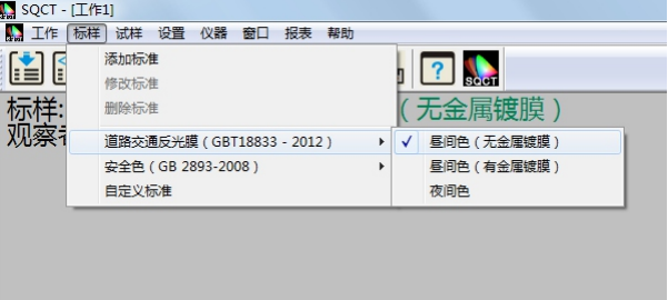
FIGURE 8
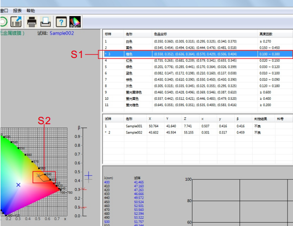
Figure 9
(5) Safety colorGB 2893 for domestic (CN) traffic signs to use more standard GB 2893, SQCT software will be the standard color gamut in the standard into it, customers only need to choose according to their own needs, the method is the same as the menu "road traffic reflective film GB/T 18 833".
On the basis of "Safe Color GB 2893", we can also choose a series of operations such as "Add Standard", "Modify Standard", "Delete Standard", etc., to change "Safe Color GB 2893" to the polygon-tolerance standard we need.
(6) Custom standards
In the case of "Road Traffic Reflective Film GB/T 18833" and "Safety Color GB 2893", we can use "Custom Standard".
As shown in Figure 10, click "Standard - > Custom Standard", the standard display area is cleared, and we create our own multi-sided descriptive difference standard through "Standard - > Add Standard".
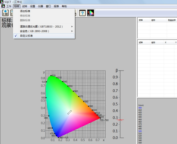
FIGURE 10
1.2 Test Preparation
(1) Install the SQCT host computer correctly
The software is installed in accordance with the "Color Management Control Software Instruction Manual" provided with the SQCT software CD-ROM.
(2) The NS808 instrument is powered on and on
Power on and start the instrument according to the "Spectrophotometer Instruction Manual".
(3) NS808 initiates communication from the menu button, and SQCT communicates successfully with NS808
According to the "Spectrophotometer Instruction Manual", the communication between NS808 and SQCT can be realized by connecting to a computer via USB.
(4) The instrument is calibrated by SQCT and the white board and black barrel are corrected in turn
According to the "Color Management Control Software Instruction Manual" provided with the SQCT software CD-ROM, the instrument is white-calibrated and black-corrected in turn.
2. Technical specifications of NS808 special Spectrophotometer for traffic road signs
| Product model | NS808 |
| Lighting method | 45/0 (45 annular uniform illumination 0 ° reception); |
| Meets standards | CIE No.15, GB/T 3978,GB 2893,GB/T 18833 |
| characteristic | It is specially used for the measurement of brightness factor and color coordinates of traffic road signs, markings and reflective films, including GB 2893 and GB/T 18833 standard colors, and can be manually customized to describe the polygon rectifier. Used for color transmission and quality control in plastics, electronics, paints and inks, textiles and garments, printing and dyeing, printing and other industries. |
| Integrating sphere size | Φ58mm |
| Illumination light source | Combined LED light source |
| inductor | Silicon photodiodes |
| Measure the Wavelength range | 400~700nm |
| Wavelength spacing | 10nm |
| Reflectance measurement range | 0~200% |
| Measure the caliber | Φ8mm |
| Color space | CIE LAB,XYZ,Yxy,LCh,CIE LUV |
| Chromatic aberration formula | ΔE*ab,ΔE*uv,ΔE*94,ΔE*cmc(2:1),ΔE*cmc(1:1),ΔE*00 |
| Other chromaticity indicators | WI(ASTM E313,CIE/ISO,AATCC,Hunter), YI(ASTM D1925,ASTM 313), TI(ASTM E313,CIE/ISO), metamerism index Mt, Colour fastness to viscosity, fastness to discoloration, strength, coverage |
| Observer perspective | 2°/10° |
| Observe the light source | D65,A,C,D50,D55,D75,F2,F6,F7,F8,F10,F11,F12 |
| display | Spectra/Data, Sample Chromaticity Values, Color Difference Values/Plots, Pass/Fail Results, Color Bias, Color Simulation |
| Measure the time | 1.5s |
| repeatability | Spectroscopic reflectance: standard deviation within 0.1% (400~700nm: within 0.2%): Chromaticity value: within 0.04 of ΔE*ab (after correction, the average value of 30 whiteboards was measured at 5 s intervals) |
| Difference between stages | ΔE*ab within 0.2 (BCRA Series II. 12 swatches measured average) |
| size | Length X Width X Height = 90X77X230mm |
| weight | Approximately 600g |
| Battery level | Lithium battery, 5000 times in 8 hours |
| Illumination source life | More than 1.6 million measurements in 5 years |
| display screen | TFT True Color 3.5inch, capacitive touch screen |
| interface | USB/RS-232 |
| Storing data | 1,000 standard samples and 10,000 samples |
| Operating temperature range | 0~40℃(32~104°F) |
| Storage temperature range | -20~50℃(-4~122°F) |
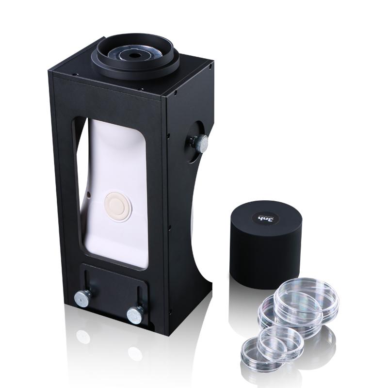
| Standard accessories | Power adapter, lithium battery, manual, CD (management software included), data cable, black and white correction cylinder, protective cover, wristband |
| Optional | Micro print holders, powder test cartridges |
| Note: It is subject to change without notice | |
3. Data testing
2.1 Test process
Before you are ready to test(whiteboard, blackboard correction), usually first establish a polygon-tolerance standard, then test the sample, and then determine whether the sample falls within the polygon-tolerance range, print the test data of the sample or export the test data of the sample, and save the test data for the next call.
2.2 Determine whether the chromaticity data of the sample meets the polygon-tolerance standard example
For example, how to determine whether the blue sample is in the blue area specified in the "GB/T 18833-2012 Road Traffic Reflective Film Sample" (no metal plating, daytime reflective film color), according to the following steps, the measurement and judgment will be completed in turn.
(1) Establish polygon-tolerance standards
SQCT directly puts the polygonal color area of "GB/T 18833-2012 Road Traffic Reflective Film Sample" into the software, and can be selected directly from the menu, "Standard Sample-> Road Traffic Reflective Film GB/T 18833-> Daytime Color (No Metal Coating)" is shown in Figure 11.
Double-click the blue color of the standard sample area, as shown in S3 in Figure 12, so that the blue is the current standard sample, and the blue polygon-tolerance standard sample (the blue area specified in GB/T 18833-2012 Road Traffic Reflective Film Sample) is displayed in the S4 part.
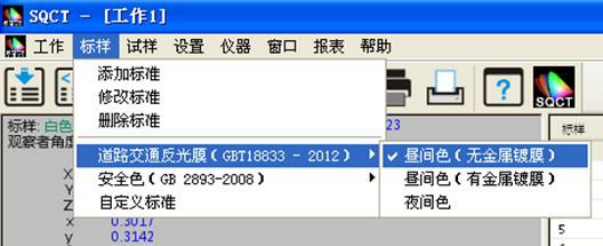
FIGURE 11
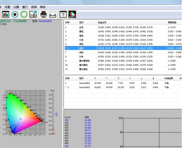
FIGURE 12
(2) Specimen test with NS808
Place the test sample on the NS808 measuring aperture, attach it tightly, and click the mouse on the shortcut tool for specimen testing, as shown in Figure 13. The test is completed in about 1.5 seconds, and the test data is shown in S5 in Figure 13, the position in the color product seat is shown in S7, and the simulation and judgment results are shown in S6.
At the same time, the test specimen can be renamed and deleted by "Specimen-> Rename/Delete".
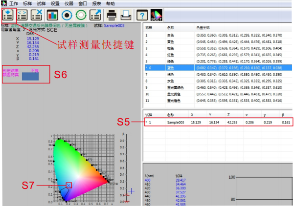
FIGURE 13
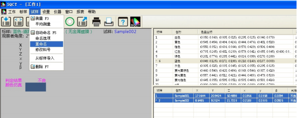
FIGURE 14
(3) Specimen test data processing
The test results of the sample can be generated through the print menu, select the sample and standard sample to be printed, and execute "Report-> Color Difference-> Print/Print to Word" or "Report->Color Difference Accumulation-> Print/Print to Word" to print out the test results, as shown in Figures 15 and 16.
At the same time, the test results can be exported in the form of EXCEL table, select the samples and standard samples to be printed, execute "File-> Export Data", export the test results in csv format, and then open them in EXCEL for data processing, as shown in Figure 17.
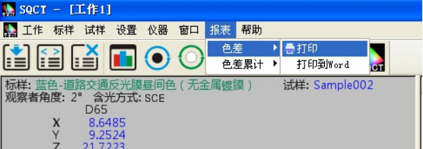
FIGURE 15
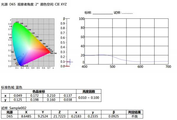
FIGURE 16
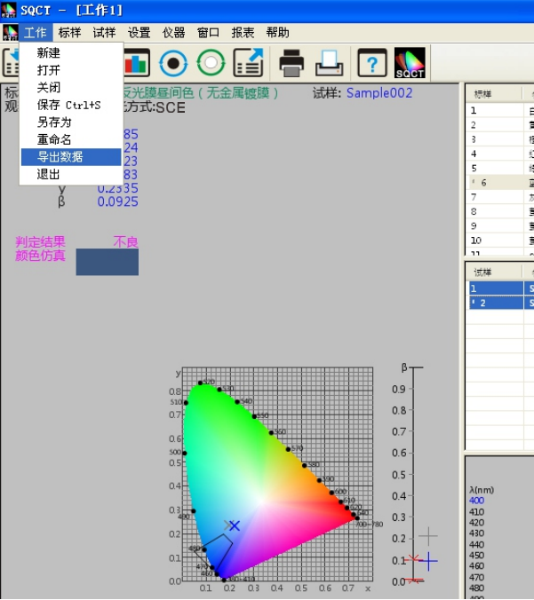
FIGURE 17
(4) Save the test data
For the test results, the measurement data and configuration files can be saved in the form of engineering by saving, so as to facilitate later call.
If you run File - Save/Save as >, the test data and configuration file will be changed to "*. job" for later calling, as shown in Figure 18.
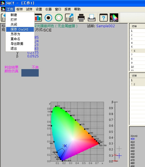
FIGURE 18
- 1JJF 1990-2022《Calibration Specification for Standard Integrating Sphere Sources》
- 2GB/T 2374-2017《Dyestuffs—General rules for dyeing test》
- 3GB/T 17001.6-2022《Anti-counterfeiting printing ink—Part 6:Infrared excitation fluorescence anti-counterfeiting printing ink》
- 4QB/T 5160-2017《Test method of artificial leather and synthetic leather一Test method for color measurement》
- 5GB/T 36650-2018《Inks for optical fiber coloring》
- 6HG/T 3951-2007《Water based colorants for architectural coatings》
- 7CY/T 205-2019《Screen printing - Pigment dispersion paste for textile printing process control requirements and test methods》
- 8GB/T 6688-2008《Dyestuffs - Determination of relative strength and color difference - Instrumental method》
- 9GB 2893-2008《Safety colours》
- 10GB/T 18833-2012《Retroreflective sheeting for traffic control》