
DAKOTA CMXDL + color screen, ultrasonic Coating Thickness Gauge
 CMXDL + color screen

DAKOTA CMXDL + color screen Ultrasonic Thickness GaugeSPEC
DAKOTA CMXDL + color screen Ultrasonic Thickness GaugeDetails
DAKOTA CMXDL + color screen Ultrasonic Thickness GaugePacking list
- SKU
- NB029555
- Measurement range
- 1.0~152mm
- Probe Frequency
- 5MHz dual crystal probe
- Probe style
- Split probe
- Probe diameter
- Φ6.35mm
- Probe line length
- 4 foot cable
- Display resolution
- +/- 0.001 inches (0.01 mm ), +/- 0.0001 inches (0.001 mm)
- unit system
- Imperial and metric systems
- Calibration method
- Single-point and two-point calibrating options for materials and coatings, or select the basic material type
- Measurement mode
- Coating off: pulse echo PE; coating on: pulse echo coating PECT; temperature compensation: pulse echo temperature compensation PETP; through coating: echo EE; through coating verification: echo only echo verification E-EV; coating: coating CT
- Measurement speed
- 0.0122 to 0.7300 in./ms (309.88 to 18542 m/s)
- Storage Capacity
- 4 Gb Internal SD Card
- Display
- 1/4 VGA AMOLED color display (320 x 240 pixels). Viewing area 1.7 x 2.27 inches (43.2 x 57.6 mm). 120 Hz screen refresh rate.
- Operating language
- English
- Interface
- Bidirectional RS232 serial port. Windows ® PC interface software.
- Environmental temperature
- 14 to 140 ° F (-10 ℃ to 60 ℃)
- Power Supply
- Three 1.5V alkaline or 1.2V NiCad AA batteries
- Operating Time
- NI-MH and alkaline batteries: gray scale 35 hours, color 12 hours. Nicad: gray scale 10 hours, color 5 hours.
- Host size
- 63.5*165*31.5mm
- Weight
- 13.5 ounces (with battery)
- Automatic shutdown
- 5 minutes free
- Certificate type
- Factory calibrated to NIST and MIL-STD-45662.
- Sensing Connector type
- Two LEMO 00 Connectors
- Additional features
- Automatic detection zeroing, recognition and temperature compensation. 64 custom setting configurations. High speed scanning with up to 50 readings per second. Audible alerts with Upper/Lower limits. Built-in differential mode for QC checking.
- pulse generator
- Double square wave pulse generator
- receiver
- Dual Receiver - Manual or AGC gain control over 110 dB. Adjustable damping (50-1500 ohms).
- Timer
- Precision TCXO with Single Pulse 100 MHz 8-Bit Ultra-Low Power Digitizer
- keyboard
- A membrane switch pad with 12 tactile keys
- Pulse echo mode (PE)
- (Pit and defect detection) Measurement range 0.63 to 1219.2 mm
- Pulse echo coating mode (PECT)
- (Material, coating, pit and defect detection): Material: 0.63 to 1219.2 mm. coating: 0.01 to 2.54 mm
- Pulse echo temperature compensation mode (PETP)
- (Pit and defect detection) Automatic temperature compensation - Measurement range 0.63 to 1219.2 mm
- Echo Mode (EE)
- Via coatings and coatings) in sizes from 2.54 to 152.4 mm
- Echo Mode (E-EV)
- Via coatings and coatings) in Dimensions of 1.27 to 25.4 mm
- Only coating mode (CT)
- (Coating thickness) 0.0127 to 2.54 mm
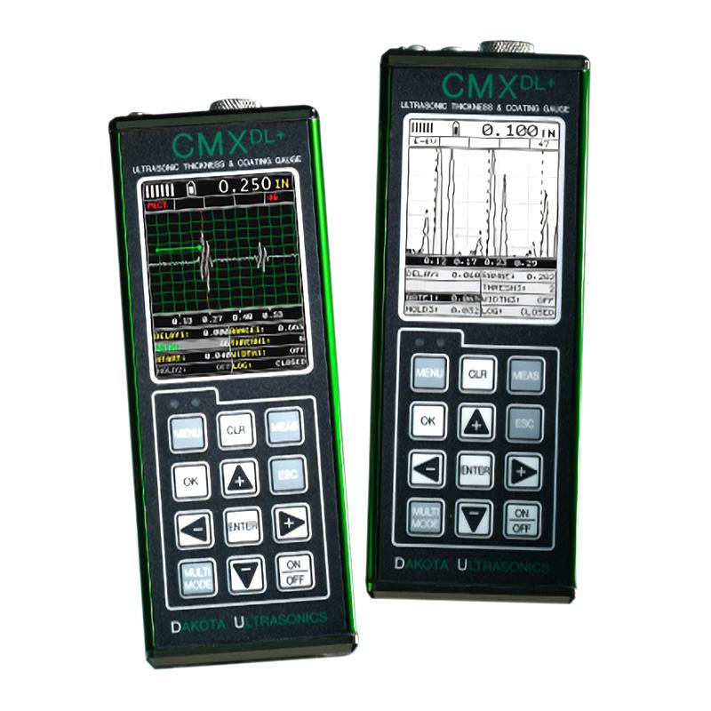
Introduction
The CMX DL+ pressure gauge has all the features of the base CMX model, plus a full-featured A-scan presentation with RF and rectifier viewing options. The CMX DL+ is equipped with 3 completely independent doors (start, stop, width and threshold). Equipped with a 110dB gain range, it adds flexibility in a wide range of sensors and applications. Optional 50 volt pulser boost or shut-off (100 – 200 volts). The color version offers a rotating portrait or landscape option to increase the viewing area of the A-scan. Our DakView Java-based PC or MAC OSX software makes the kit truly the Cadillac of the CMX series.
Diagram of the display structure
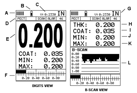
A. Repeatability/Stability Indicator – This indicator should generally be used in conjunction with the numeric thickness values displayed. When all vertical bars are fully lit and the last digit of the digital thickness value is stable, the CMXDL+ reliably measures the same value approximately 250 times per second (250 Hz), depending on the measurement mode and function enabled.
B. Battery icon – indicates CMXDL+ remaining battery life.
C. Speed – CMXDL + material velocity value currently in use or calibrated. Displayed in imperial or metric units, depending on the unit of the gauge.
D. Feature Status Bar – Indicates the features that are currently enabled and in use in the following order:Measurement Mode,Difference mode,High-speed scanning mode,Alarm mode,Gain setting.
E. Numeric Material Thickness Values – Extra-large font size for easy viewing.
F. Scan Bar – Another view of the material thickness in the horizontal bar of the deflection style. This is a vision tool that enables users to see thickness changes from defects and pits during high-speed scanning.
G. Units – The units of measurement (imperial, metric) currently in use.
H. Numeric Material Thickness Values – Smaller font size when B-scan display view is enabled.
I. Coating Thickness Value – Shows the actual thickness of any coating adhering to the surface of a metallic material (PECT mode) or the actual thickness of the coating adhering to a non-metallic surface (CT mode).
J. Minimum material thickness – part of the scanning function. Displays the minimum thickness value found during the scan.
K. Maximum material thickness – part of the scanning function. Displays the maximum thickness value found during the scan.
L. B-scan display – a cross-sectional view of the material. Provide the user with a graphical view of the relative/blind surface (i.e., the inner surface of the pipe wall) to give the user an idea of the condition or integrity of the material being measured.
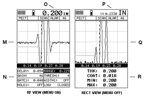
M. RF A-scan display – the actual acoustic reflection returned from the inspection of the opposite surface of the material being measured. In this view, the entire sine wave is displayed, along with both positive and negative half-cycles after detection/reflection. This view is often used to initially "see the big picture" and fine-tune the oscilloscope settings before selecting another view option.
N. Hot Menu Items – We refer to this menu section as "Hot Menu" because these are commonly used adjustment functions that require quick access from the user. They can be displayed and scrolled by pressing the MEAS key at any time. The ESC key is used in conjunction with the MEAS key to reverse the scroll direction.
O. Reference Description – The substrate thickness value displayed at the reference point "O" when the Hot Menu item is displayed/activated. However, when the Shortcut Menu item is disabled, the current substrate velocity value is displayed, as shown by the reference point "P". When the "popular menu"
When deactivated, the entire "Hot Menu" section will turn into a multi-measurement display area, allowing the user to view at the same time: a dynamic display of min/max thickness values for the base material, coating and base material, as indicated by the reference point "R".
P. Reference Instructions – Please refer to "O" for detailed instructions.
Q. RECT A-scan showing – the actual acoustic reflection returned from the inspection of the opposite surface of the material being measured. In this view, only half of the sine wave (positive or negative) is displayed.
Once the user has made all the necessary adjustments using the RF mode (see M), the view is often referred to as the "Defect Detection" mode.
R. Reference Instructions – Please refer to "O" for detailed instructions.
- 1Use of Ultrasonic Thickness Gauge and its indication
马景铎; 马天燕 - 《如何正确使用超声波测厚仪》
- 2Principle of Portable Ultrasonic Thickness Gauge
- 3Measurement principle and influencing factors of high temperature ultrasonic Thickness Gauge
- 4Types and Usage Methods of Coupling Agent for Thickness Gauges
- 5The Principle, Application and Precautions of Copper Plate Ultrasonic Thickness Gauge
- 6Principle, Application and Selection of Ceramic Ultrasonic Thickness Gauge
- 7Principle, Application and Type Selection of Electronic Coating Thickness Gauge
- 8Principle, Application and Type Selection of Ultrasonic Thickness Gauge
- 9Principle, Application and Type Selection of Ultrasonic Thickness Gauge
- 10Four Methods of Ultrasonic Thickness Gauge measurement