
Yongxin ZHS-4 Paper and Cardboard thickness Tester
SE ZHS-4 digital display

-
 CCYONGXIN ZHD-4 Paper and Cardboard Electric Thickness Gauge$ 818.00SE
 -
 PY-H606A Paper Film thickness Tester 4mm/0.001mm$ 413.00SE
 -
 CHINA NBC-5634 paper Cardboard Thickness Gauge Graduation 0.001mm$ 485.00SE
 -
 CHINA NBC-5634 Cardboard Thickness Gauge, percentile 0.01mm$ 438.00SE
 -
 YINUO YN-HDY01 Paper Thickness Tester 0-4mm 0.01/0.001$ 439.00SE


ChangChunYongXin ZHS-4 digital display Paper and Cardboard thickness TesterSPEC
ChangChunYongXin ZHS-4 digital display Paper and Cardboard thickness TesterDetails
ChangChunYongXin ZHS-4 digital display Paper and Cardboard thickness TesterPacking list
- SKU
- NB034359
- Measuring range
- 0~4mm
- Contact Pressure
- 100 ± 10kPa
- Contact area
- 2±0.05cm²
- Dimensions
- 240*160*120mm
- Weight
- 4.5kg
- Display
- digital display

Application
The instrument is suitable for measuring the thickness of various paper, cardboard and other sheet materials below 4mm.
Principle
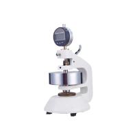
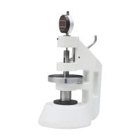
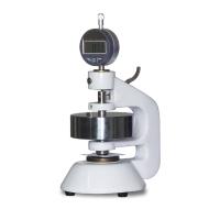
This instrument is a special instrument for measuring the thickness of paper and cardboard with the internationally accepted Schopper type, which is designed on the principle of contact measurement.
Thickness refers to the vertical distance of paper and cardboard under a certain pressure between two measuring boards, and the result is expressed in mm or um. According to the thickness and thinness of the paper, multi-layer measurement or single-layer measurement can be taken, and the result of single-layer indicates the thickness of the paper. The instrument is divided into the following four sections:
1. Paper pressing mechanism: composed of heavy thallium (2), measuring head (3), and measuring anvil (4), used to form a specified pressure on the sample.
2. Indicating mechanism: it is a standard dial indicator (8). Its measuring rod is in contact with the upper end surface of the measuring head, so that the measured thickness can be read by converting the displacement of the measuring rod into the rotation angle of the pointer. The installation of the dial indicator is to point the small pointer of the dial indicator to 1.000mm as the zero point of the Thickness Gauge, so as to make full use of the accuracy of the gauge (the error of the dial indicator is the smallest within the range of 1.000~1.100mm).
3. Lifting mechanism: It is composed of a lever (5) and a small shaft (6), which is used to lift the measuring head so that it can be put into the sample for measurement.
4. Connecting mechanism: It consists of a base (1) and a fastening screw (7), which is the base of the instrument and the structure connecting the three parts above.
This instrument clamps the sample between the measuring head and the measuring anvil. The lower end surface of the measuring head has a contact area of 2cm², and the sum of the weight, the gravity of the measuring head and the spring force of the dial gauge produces a contact pressure of 100kPa. When a certain material is pressed between the measuring head and the measuring anvil, the measuring head moves a distance equal to the thickness of the material, and this displacement is transmitted to the gauge rod, and after being amplified by the gear mechanism in the gauge, it is transformed into a pointer The angle of rotation gives the reading value of thickness.
Installation and commissioning
(Digital display dial indicator, dial indicator view manual)
Place the instrument on a level table, the height of the table is such that the center of the instrument dial is at the same level as the operator's eyes.
1. Zero point adjustment
(1) Press the lever with the left thumb to raise the measuring head.
(2) Evenly and slowly loosen the lever, drop the measuring head until the measuring surfaces touch each other, and take your hand away from the instrument.
(3) Observe whether the big pointer points to zero and whether the small pointer points to 1.
(4) If the big pointer is not at the zero point, turn the dial of the watch slightly to make it zero.
(5) Repeat the above steps several times, the large pointer should be stable at zero. If the large pointer is not at the zero point, but is too far away from the zero point, adjust according to the following steps:
(a) Turn the zero point of the watch dial to the highest position.
(b) Loosen the screw (7) with a screwdriver.
(c) Move the dial indicator up and down until the big pointer points to zero and the small pointer points to 1.
(d) Use a screwdriver to properly tighten the screw (not too loose or too tight, the watch will be inaccurate if it is too loose, and the flexibility of the movement of the watch stem will be affected if it is too tight.
(e) Turn the dial dial slightly to zero accurately.
2. Calibration of indication accuracy:
(1) Loosen the screw (7), pull the watch out 1mm from the sleeve so that the small pointer indicates zero, the big needle goes up vertically, and tighten the screw.
(2) Set the meter to zero accurately.
(3) Use 1.000, 1.010, 1.012, 1.020, 1.022, 1.100, 1.200, 2.000, 3.000, 4.000, 5.000mm block gauges instead of samples for operation.
(4) Find out the difference between the reading and the block gauge.
(5) Subtract 1mm from the difference measured at each point, and the resulting difference is the error of each point when 1 is used as the zero point. This error should be within the range of the following table:
| Measuring range | dial gauge reading | Allowable error |
| (mm) | (mm) | (mm) |
| 0-0.100 | 1.000-1.100 | ±0.005 |
| 0.100-1.000 | 1.100-2.000 | ±0.008 |
| 1.000-4.000 | 2.000-5.000 | ±0.012 |
If the error is too large, the dial indicator should be replaced and re-calibrated, and then every six months.
2. Verification of parallelism
Measure a clamped steel ball at the front, back, left, right and four points near the edge and the center point respectively. It should be noted that the five measurements are all at the same point of the steel ball, and the maximum difference between the five readings obtained Should be less than 0.005mm.
operating procedures
1. Measurement
(1) Press the lever (5) with the left thumb and lift the measuring head (3);
(2) Put the sample to be tested between the measuring head (3) and the measuring anvil (4) with the right hand, and the sample needs to completely cover the measuring surface;
(3) Loosen the lever (5) evenly and slowly, drop the measuring head until it touches the sample, completely relax the thumb, and leave the hand away from the instrument;
(4) Record the reading on the dial, the small pointer indicates an integer in millimeters, and the large pointer indicates a decimal in millimeters;
(5) Press the lever (5), lift the measuring head (3), take out the sample, repeat the above steps, and measure at least three different points on the same sample.
2. Result processing
The readings obtained on each sample were averaged and the arithmetic mean was taken.
Maintenance and Troubleshooting
1. When not in use, the instrument should be placed in a glass cover or a plastic bag to prevent dust from falling on the measuring surface.
2. The end face of the measuring head and the top of the measuring anvil are to prevent collision and corrosion. Before and after each measurement, wipe it with gauze.
3. After the measuring head is raised during measurement, it should be allowed to fall gently under the action of gravity to prevent the instrument from being damaged due to excessive impact force.
4. The lifting height of the measuring head should not be too high.
5. Clean and oil the instrument regularly.
6. If the measuring head and measuring anvil surface are corroded, the instrument should stop using. Then loosen the screw fixing the measuring anvil (4), remove the measuring anvil, measuring head (3) and weight (2), and grind the measuring surface. After reassembly, the inspection method is carried out according to the three steps of adjustment, and the inspection is qualified
The instrument can only be used after passing the inspection.
- 1Basic Principle and Application of Cardboard Strength Testing Machine
- 2 The function and role of packaging
- 3Paper and Cardboard Thickness Gauge