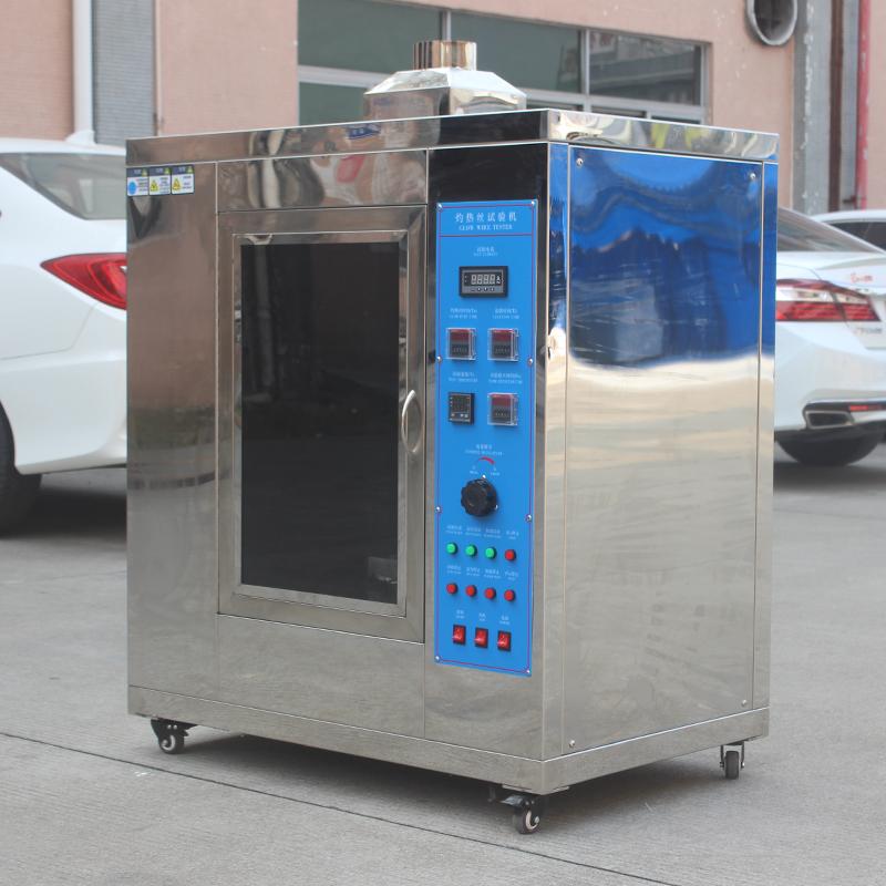

CHINA ASR-4324 Glowing Wire Tester, Stainless Steel Housing
 ASR-4324

AISRY ASR-4324 Glow-Wire TesterSPEC
AISRY ASR-4324 Glow-Wire TesterDetails
AISRY ASR-4324 Glow-Wire TesterPacking list
- SKU
- NB036379
- Test space
- 0.5M3 ,深x宽x高60x95x90cm
- Dimensions
- 宽x深x高113x57x120cm
- glowing wire
- 4.0Mm diameter ring made of nickel/chrome wire
- Thermocouple
- 0.5Mm armored filament Thermocouple, capable of withstanding high temperatures of 1050 ℃
- Heating current
- When the temperature is 960 ℃, the current is between 120 and 150A
- The force applied to the test
- 0.8~ 1.2N, and limit the pressing depth to at least 7mm
- Timer
- Ignition duration (Ti) and flame extinguishment time (Te) can be recorded
- Glowing wire temperature
- 500~1000 ℃, digital display adjustable
- Temperature tolerance error
- +/- 10 ℃ (500~750 ℃), +/- 15 ℃ (750~1000 ℃), the temperature is +/- 0.5 grade
- Shell material
- stainless steel
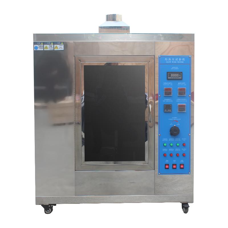
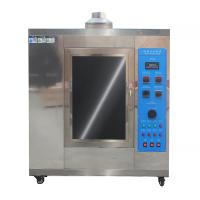
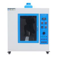
Parts of electrical and electronic equipment may be exposed to overheating stresses due to the action of electricity, and their deterioration may reduce the designEquipped with safety features. These parts should not be excessively affected by the heat and fire generated inside the device. It is easy to make inside the deviceParts of insulation or other solid combustible materials where flames spread may ignite due to glow wires or glowing components. at- -Ignition occurs under certain conditions, such as fault currents flowing through the wires, component overloads, and hot components that come into contact with them. This testThe Tester simulates a heat or ignition source such as a glowing component or overload resistance under fault or overload conditionsIt simulates the creation of a heat or ignition source such as a glow component or an overload resistor in a short period of time under fault or overload conditionsThe thermal stress is used to assess the fire hazard of the product. It is suitable for electrical and electronic products, household appliances and their materialsFire hazard test and combustion performance test. This Tester is based on IEC60695-2-10/11/12/13,IEC60669-1、1EC60884-1、 UL1598、 GB5169. 10、GB5169. 11 and GB4706.1. "Home and SimilarThe relevant provisions specified in the safety of electrical appliances for use, Part I: General Requirements, are designed and manufactured.
Operating Principle
The Test Chamber is divided into two parts, the left part is the glow combustion chamber, the right part is the electrical control room, and the sample is loaded into the sample fixture.Driven by a motor, it can travel front and rear and is automatically controlled during the test. The glow wire is fixed and moves to the right by the specimen trolleyto the glow wire head, and pull the trolley with a weight, so that the applied pressure is kept IN, and the limiting device limits the depth of pressing7mm. The glow wire application time Ta (T1) is preset by a digital time relay. The number of flame ignition time Ti (T2).The display time relay measures and is controlled by a pushbutton switch. The flame extinguishing time Te (T3) is measured with a digital time relay, byPush button switch control. The electrical control system uses temperature control to control the amount of glowing current to change the level of burning temperatureThe instrument accurately controls the glow wire temperature, and the K-type armored thermocouple has high precision and high reliability.
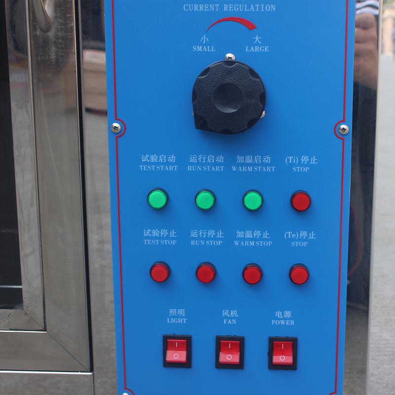
Appliance control panels
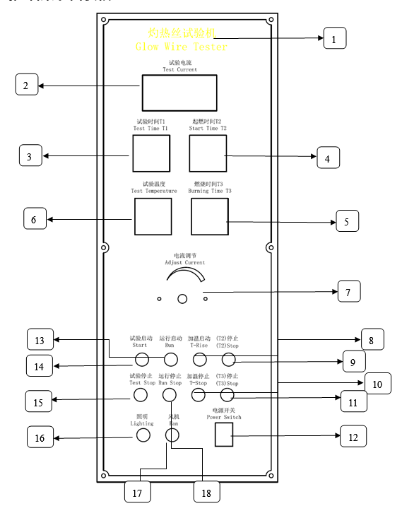
1) The name of the testing machine
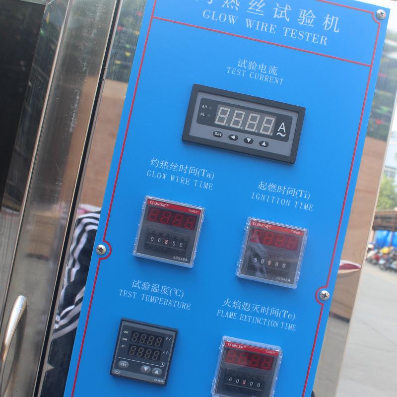
2) Ammeter - indicates the glow wire current size
3) Timer T1: Test (Glow) Time (Ta) - A timer for the time to burn the sample
4) Timer T2: Glow Ignition Time (Ti) - Sample flame ignition time
5) Extinguishing time T3(Te) - Press this timer when the sample flame is extinguished
6) Temperature Indicator - Displays the set temperature and scorching temperature
7) Heating current regulator - adjust the heating current size
8) Heating start switch (T-rise) - Press this switch button to adjust the current level
9) Ignition timing stop switch (T2 stop) - Press this switch button to stop the timing on T2 and start timing on T3
10) Heating stop switch (T-stop) - Press this switch button to stop heating
11) Combustion timer stop switch (T3 stop) - Press this switch button to stop the timer on T3
12) Power Switch - Press this switch button to turn on the glow wire testing machine
13) Run Start - Press this switch button to start the specimen trolley to move
14) Test start-press this switch button to enter the state of the glow testing machine
15) Test Stop - Press this switch button to enter the test end state of the glow testing machine
16) Light Switch - Control the light
17) Fan switch - control the fan to extract exhaust gas
18) Run Stop - Press this switch button to stop the specimen trolley from moving
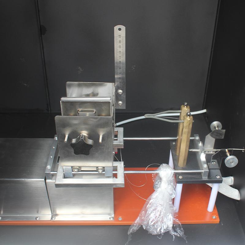
Glow wire structural components
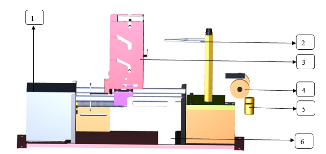
1) Power drive
2) Glow wire probe
3) Specimen trolley
4) Weight pulleys
5) 1N weights
6) Limit switch
Precautions
When the glow wire heats up, please close the door to observe to avoid burns.
The power supply should be a three-pole socket with a ground wire to ensure reliable grounding.
Pay attention to the thermocouples and glow wires that protect the thermostat. Be careful not to damage the lumps at the top of the glow wire
Thermocouples, thermocouples are consumables and are not covered by the warranty.
When replacing a thermocouple, be sure to pay attention to the polarity.
The light switch and extraction switch cannot be turned on during the scorching process
If you find that the flame of the burning material is too large, turn off the power switch immediately, unplug the power cord, and immediately use a fire extinguisher to extinguish the fire