


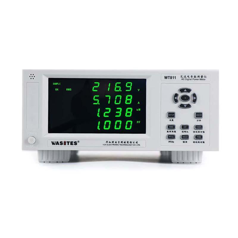
Wasites WT811 AC parameter Measurement Instrument, harmonic type, Voltage, current Power Power factor Frequency
SE WT811
WT811

Wasites WT811 AC paraMeter Measurement Instrument (harmonic type)SPEC
Wasites WT811 AC paraMeter Measurement Instrument (harmonic type)Details
Wasites WT811 AC paraMeter Measurement Instrument (harmonic type)Packing list
- SKU
- NB047978
- Measurement range
- 3~ 600V (75V/150V/300V600V) (automatic range)
- Measurement range
- 0.005A~ 20A (5/2/8/20A) (automatic range)
- Power Measurement range
- 0. 01~12KW
- Power factor Measurement range
- -1. 000~1. 000
- Frequency Measurement range
- Fundamental 40-130Hz, Bandwidth 5KHz
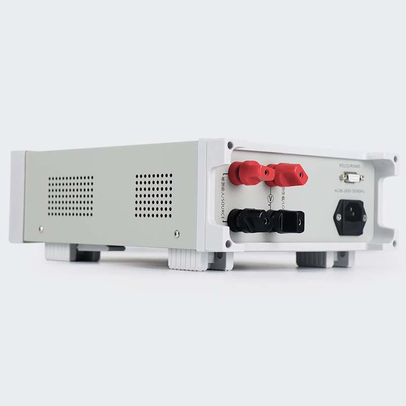
- Input Impedance
- Voltage greater than 5MΩ, current less than 0.02Ω
- Continuous maximum allowable input
- Voltage 700V, Current 24A
- Instantaneous maximum allowable input
- 1000V, 40A (time 1S)
- Automatic Range Upshift
- Measured value exceeds approximately 110% of rated range
- Automatic range downshift
- Measured value less than about 30% of rated range
- Measurement update speed
- Normal mode: about 2 times/second, Harmonic mode: about 1 time/2 second
- Sorting alarm function
- With current, Power settings, Upper/Lower limit alarm function, alarm delay.
This electrical parameter Tester uses high-speed DSP processor + phase-locked loop (PLL) for data analysisThe Voltage/current is sampled by low-temperature bleaching resistance or high-precision transformer, so that the sampling signal is not overfiltration, which ensures the stability and accuracy of the measurement data. Has a True Rms (RMS) measurement. rootThe instrument can measure Voltage, current, power, power factor, frequency, Voltage crest ratio, and current wavePeak ratio, also with harmonic analysis, serial communication and other functions. The instrument has perfect functions and performanceSuperior and simple operation, it can meet the high-speed measurement at the production site and also meet the needs of the laboratoryand R&D measurement needs.
It is widely used in lighting appliances, power tools, household appliances, motors, electric heating appliances and other collarsProduction lines, laboratories, and quality inspection departments of production enterprises.
According to the actual needs of the user, a variety of measurement functions can be customized to meet higher applications.
peculiarity
Four windows simultaneously display Voltage, current, power, power factor/frequency
Using high-speed DSP+PLL design, it can accurately calculate the harmonic distortion and absolute value of Voltage and current.
The use of zero magnetic flux current Detector has a high measurement bandwidth, which effectively ensures the accuracy and stability of measurement
Data locking, alarm mute function
It can be set arbitrarily. The upper and lower limit alarm parameters, sound and light alarm function, and can set the qualified or unqualified alarm function, and can set the delay alarm. Batch detection improvedefficiency
Principle
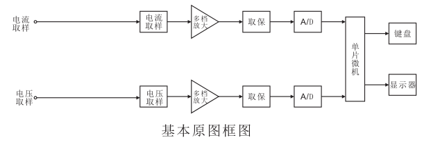
As shown in the figure, the instrument consists of an analog part and a digital part. The analog part is mainly composed of sensingdevice, multi-gear programmable amplifier, sampling and holder, A/D and other circuits. The numerical part contains micrometersIt consists of a computer data memory, a keyboard, and a monitor.
After the measured Voltage signal passes through the Voltage sensor, the signal is reduced to a weak signal, and the signal is largeSmall, controlled by a microcomputer, programmable multi-range amplification, and by a sample-holder, byThe analog/digital converter A/D converts the Voltage signal into a digital signal and transmits the digital signal to the miniatureThe computer calculates the true RMS Voltage (URMS) and outputs the value to the display on the display.After the measured current signal passes through the current sensor, the signal is converted into a weak Voltage signal, which is the same as the measured signalThe Voltage is the same, after multi-gear selection of program-controlled amplification, sampling and holding, A/D conversion, in the microcomputercalculates the True RMS Voltage (IRMS) and outputs the value to the display.