
MODERNER LBN-III Falling Rod Viscometer
 LBN-III

Moderner LBN-III Falling Rod ViscometerSPEC
Moderner LBN-III Falling Rod ViscometerDetails
Moderner LBN-III Falling Rod ViscometerPacking list
- SKU
- NB049676
- Instrument control box input Power Supply
- DC24V
- External power adapter input Power Supply
- AC110-220 50/60Hz
- Applicable apparent viscosity range
- 2~200Pa·s
- Nominal diameter of guide sleeve and nominal outer diameter of falling rod
- 12mm
- Drop Mass
- 132g
- Weight group grams
- 25-50-100 -200-200-500-1000-1000-1000g (total 4075g)
- Host Dimensions
- 140×140×300mm
- Packaging Dimensions
- 620×350×215mm
- Weight
- 18Kg (including instrument, Weight box, control box)
- Gross Weight
- 14.8kg
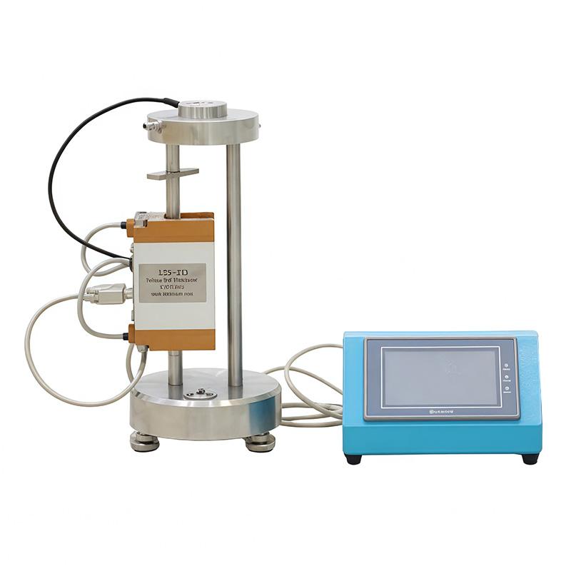
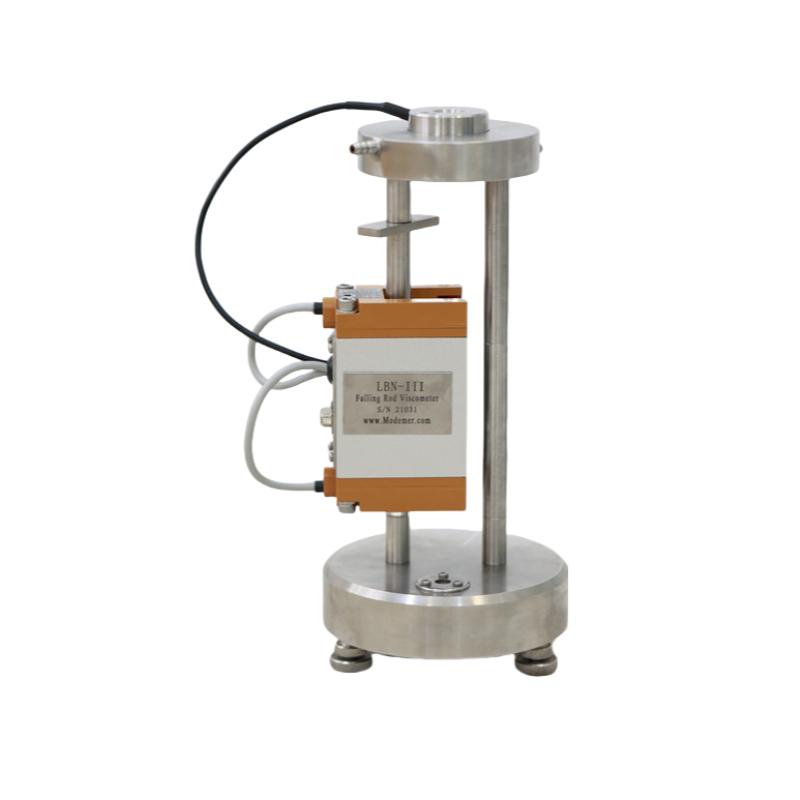
A drop rod viscometer (also known as a larey viscometer) is a commonly used instrument for determining certain rheological properties (apparent viscosity, false yield value, shortness, etc.) of non-Newtonian fluids (fluids whose viscosity varies with shear rate) such as printing inks. It is generally believed that the results of the Lalei drop rod test can ideally describe the partial rheological properties of the ink in the printing process, which is suitable for the actual control of viscosity during the production of ink, and is often used as a technical requirement for acceptance by buyers and sellers. LBN-III drop rod viscometer is designed and manufactured with reference to the international standard ISO12644: 1996 (E) "Printing Technology - Determination of Rheological Properties of Slurry Ink and Its Connecting Materials by Falling Rods Viscometer", and its principle is: to measure the required fall time of heavy drop rods with different loads through the pores coated with test samples, with the help of an appropriate flow model (Carson model, Bingham model or exponential law model), by applying a linear regression method to obtain the apparent viscosity of the sample (viscosity value at a certain shear rate, The apparent viscosity obtained by the puller drop test is sometimes referred to as the puller viscosity), the yield value, and the shortness ratio (often referred to simply as shortness).
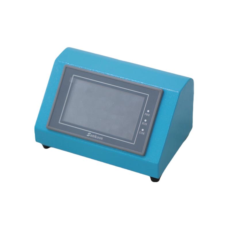
On the basis of the old model, the LBN-III drop rod viscometer adds the function of directly displaying the calculation results of the exponential law model in the control box. The old model instrument control box only displays the falling temperature and falling seconds during the rod drop test, and the calculation of each model is completed by using the computer EXCEL calculation table. In order to facilitate the user's use, the new model instrument is improved to complete the model calculation and display by the touch screen of the control box.
Operational preparation
1. Take the instrument out of the box and place it on the workbench to adjust the level of the instrument.
2. Plug in the plug of the signal connection line and insert the temperature sensor into the inclined hole of the rod guide sleeve.
3. Connect the two latex pipes drawn from the constant temperature Water Tank (need to be purchased separately) with the constant temperature water jacket respectively.
4. Turn on the power supply, turn on the power switch of the thermostatic sink and the instrument control box, the display screen shows that the temperature is the Celsius temperature of the current guide bushing, and the time display is 0.00 seconds.
(Note: The specific operation method of the thermostatic sink is shown in the manual of the thermostatic sink.) )
5. The laboratory temperature should be kept at 25°C±2°C during the whole measurement period. When the guide sleeve temperature reaches 25°C ± 0.2°C specified in the standard, the measurement can be started.
6. In order to reduce the temperature caused by the human body temperature as much as possible during operation, it should be avoided to contact the falling rod and guide sleeve of the viscometer with bare hands. Wear gloves or pad a small piece of cotton cloth in your hand when you need to touch the drop rod and guide sleeve.
Operational summary
1. Before the measurement, take about 5g of the measured sample each time, mix it evenly on the glass plate with a small ink knife, and check that there are no coarse particles and debris. The amount of the sample to be measured should be sufficient to cover the annular groove of the drop rod guide bushing.
2. Insert the drop rod vertically into the guide bush hole of the drop rod and gently descend to the rotating baffle. Use a plastic ink knife to spread the evenly mixed test sample in the groove of the drop rod and the annular hole of the guide bushing; Gently rotate the drop rod so that the measured sample is evenly distributed around the groove; At the same time, you can gently lift the drop rod about 20 mm from the bottom of the drop bar with your fingertip to bring the test sample as close to the bottom of the groove as possible, and release your finger to let the drop bar fall to the rotating baffle to ensure that the groove is full of the test sample.
3. The optional load weight is placed on the top of the falling rod, and the rotating baffle is removed to make the falling rod fall, so that the measured sample wets the falling rod and the guide bushing; At the same time, please confirm that the photoelectric switch and temperature sensor are working normally (the temperature is fixed when falling, and the temperature is displayed as the temperature at the beginning of the fall, and the time is displayed as the fall meter; The temperature at the end of the fall is displayed as the temperature at the end of the fall, and the time is displayed as the actual number of falling seconds; After pulling up the drop rod, the temperature recovery is displayed as the measured temperature of the guide bushing, and the time is automatically cleared).
4. Avoid any operation that may scratch the falling rod, and it is not allowed to use a metal scraper to operate the falling rod; It is not allowed to fall without the test sample. Once the drop is complete, gently pull up the drop bar and rest it on the rotating baffle. Use a plastic ink knife to scrape the ink off the drop rod and apply it to the lower part of the drop stick and in the annular groove of the guide bush.
5. Select the appropriate combination of load weights: select the weights according to the above 3~4 steps for the drop test, so as to confirm that the falling time of the selected large load weights is within the range of 4~10 seconds (the American standard ASTM D4040-05 recommends that it be as close as possible to 1~2 seconds), and the falling time of the rest of the weights does not exceed 60 seconds. Usually 4~5 load weight combinations of different weights are selected.
The ISO standard recommends the following combinations of load weights: (unit: g)
| A | 5000 | 4000 | 3000 | 2000 | 1000 |
| B | 3000 | 2000 | 1500 | 500 | |
| C | 1500 | 1000 | 800 | 500 | |
| D | 800 | 600 | 400 | 200 | |
| E | 400 | 300 | 200 | 100 | |
| F | 200 | 100 | 50 | 0 |
6. The measurement of the measured sample starts from the heavy weight in the weight combination, and the weight weight must be at least two times falling time difference of no more than 0.5 seconds, and then the light weight can be replaced in turn for measurement. Before starting the measurement, prepare the tested sample according to the above 1~2 steps; Each time the drop is completed, the ink on the drop bar must be scraped off with a plastic ink mixing knife and applied to the lower part of the drop stick; The measured sample shall not be added to the measurement; If it is found that the measured sample is not enough during the measurement, clean the drop rod and guide bushing, and then take a new measured sample and repeat the above steps 1~2. The weights of each weight were measured 3 times, and the time of falling of the rod (accurate to 0.01 seconds) and the temperature of the guide sleeve (accurate to 0.1°C) were recorded each time.
7. The measurement operation should be rapid and uninterrupted, and the whole operation should be completed within 5 to 10 minutes. Many printing inks and binders contain highly volatile solvents, and unless the actual exposure time is strictly controlled, the volatilization loss during operation can cause large deviations in the measurement results. If it is found that the falling rod of the same load weight will be longer several times in a row, it means that there is a significant volatile loss (at this time, it is advisable to choose a heavier weight combination to reduce the measurement time).
8. Viscosity determination has a strong sensitivity to temperature, so the temperature must be controlled and monitored during the measurement process. In principle, if the temperature of the guide sleeve exceeds 25.2°C before operation, the temperature control device must be reset, and if the temperature of the guide sleeve changes by more than 25°C ±1°C during the whole measurement, the test must be redone.
9. After the measurement is completed, the cleaning and maintenance of the instrument should be done in time, especially the cleaning of the rod and guide sleeve must be timely, careful and thorough. Cleaning should be done using a lint-free cloth or paper and an appropriate solvent.
10. The instrument should be calibrated before leaving the factory and after a certain period of time, if the measured viscosity of the instrument is 20% different from the viscosity data of the calibration oil, the combination of the falling rod and the guide sleeve must be replaced, if the difference is not more than 20%, the viscosity correction coefficient can be used to compensate.