
MODERNER TCJ-II 1m Elastic Impact Tester Paints, varnish Dry-Film cracking performance
SE TCJ-II 1 meter

Moderner TCJ-II 1 meter Elastic Impact TesterSPEC
Moderner TCJ-II 1 meter Elastic Impact TesterDetails
Moderner TCJ-II 1 meter Elastic Impact TesterPacking list
- SKU
- NB000643
- Impact mode
- Spherical ball impact
- Impact height
- 0~100cm
- Drop Weight Mass
- 1000g
- Additional Mass
- 1kg/2Lbs
- Striker Diameter
- Φ15.9mm、Φ20mm
- die base aperture
- Φ16.3mm、Φ27mm
- Dimensions
- 300*300*1400mm
- Net Weight of instrument
- 19kg
How elastic impactors work
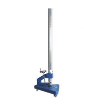
The TCJ-II Elastic Impact Tester is used to test the resistance of the dry film of the basecoat, varnish or related products to crack or peel off the substrate under standard conditions when it is deformed by a heavy hammer impact.
Standards:IGB/T1732;GB/T 20624.2;GB/T 17657;GB/T 18102;ISO 6272-2;GB/T 20624.1;ISO 6272-1;GB/T 17657;GB/T 18102
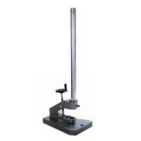
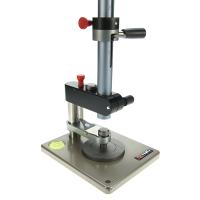
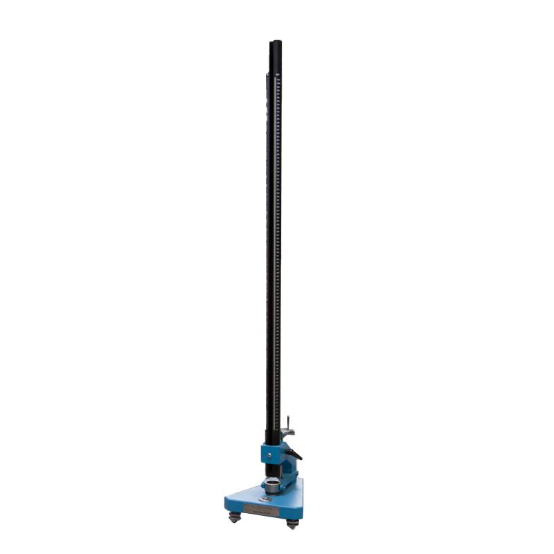
TCJ-II elastic impactor real shot
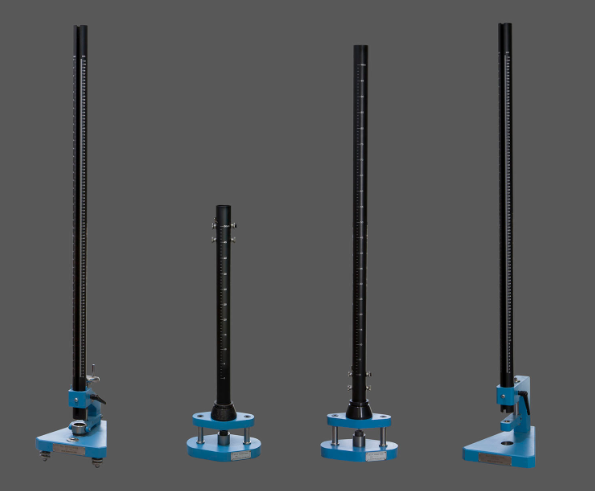
Structure and specifications of the elastic impactor
1. Structure:
The elastic impact Tester is mainly composed of a conduit (1), a height limiting ring (2), a handwheel (3), a bracket (4), a base (5), a leveling foot (6), a horizontal bubble (7), a compression sleeve (8) for pressing the test plate, and a locking handle (9). There are two types of graduations on the catheter, centimeters and inches, corresponding to ISO and ASTM standards, respectively.

2. Specifications
a. Base size: 300mmx240mmx35mm
b. Catheter height: 1265mm
c. Heavy hammer and die base
| numbering | illustrate |
| ISO100 | Drop weight 1kg in accordance with ISO ball diameter 20mm |
| ISO101 | Die holder numbered ISO 100 according to ISO inner diameter 27 mm |
| ISO200 | Additional weight 1 kg for ISO 100 is attached to falling weights |
| ASTM100 | Drop Weight 2 lbs per ASTM Ball Diameter 0.625in (15.9mm) |
| ASTM101 | Die holder for numbered ASTM100 I.D. 0.64in (17mm) |
| ASTM200 | Additional weight for numbered ASTM100 2 lbs attached to falling weights |
d. A set of depth control rings
One base ring, one ring with a thickness of 1mm, 2mm, 4mm, and 5mm, which is used to control the depth of the hammer indentation 2-10mm.
3. Weight: 18kg
Test test of elastic impactor
(1) Test preparation:
1) Visual lens: magnification is 10x, bring your own.
2) Requirements for test boards: Unless otherwise agreed, the substrate should be metal and meet the requirements of the standard. The test board should be flat, without deformation, and the thickness should be at least 0.25mm. The size of the test board should allow at least 5 different parts of the board to be tested, each part is not less than 20mm away from the edge of the board, and the distance between each part is not less than 40mm. The treatment, painting, and drying of the test plate after painting must be carried out in accordance with the prescribed method. The thickness of the coating must also be measured in accordance with the regulations, and only the test board with a paint film thickness value of no more than 10% of the specified or agreed film thickness can be used at the part to be tested or as close as possible to the test site where the test is to be carried out.
3) Unless otherwise agreed, the test shall be performed at (23±2) °C and (50±5)% Relative Humidity.
4) Select the corresponding mold base according to the required standard and put it into the hole on the base (5).
5) Select the corresponding hammer according to the selected mold base, and put the hammer from the top of the conduit (1).
6) Put the height limit ring (2) from the top of the catheter and fix it with screws.
7) Adjust the instrument level by adjusting the horizontal foot (6) and the horizontal bubble (7).
(2) Test steps:
a. Pass/Fail Test:
1) Adjust the height of the height limit ring (2) so that the scale specified by it is just in line with the specified drop weight height. If necessary, install a depth control ring with a total thickness that meets the indentation depth agreed upon by both parties or otherwise specified.
2) Put the test plate on the mold base, so that the painted side is up or down, so that the indentation can be concave or convex, turn the handwheel (3) to make the hold-down sleeve (8) compress the test plate, and loosen the heavy hammer to make it fall to the test plate.
3) Inspect the coating with a lens and observe whether the coating has 0 cracked or peeled off from the substrate, and whether the substrate has cracked.
4) Repeat the test four more times at different positions of the test plate (a total of 5 drop points), if at least 4 test points are not cracked or peeled off the substrate, then the coating is qualified.
b. Grading test:
1) Adjust the height of the height limit ring (2) so that the scale specified by it is in line with the specified drop weight height, at which no damage should be expected. If necessary, install a depth control ring with a total thickness that meets the indentation depth agreed upon by both parties or otherwise specified.
2) Put the test plate on the mold base, so that the painted side is up or down, so that the indentation can be concave or convex, turn the handwheel (3) to make the hold-down sleeve (8) compress the test plate, and loosen the heavy hammer to make it fall to the test plate.
3) Remove the test plate from the device to observe the cracking of the coating in the impact area, if there are no obvious cracks, then operate at a greater height until cracks are observed, depending on the weight used, 1 kg (2 pounds) depending on the weight used, and the height increments are 25 mm (1 inch) or 25 mm (1 inch) respectively. If cracking is not observed at the maximum height allowed by the weight, repeat with 2 kg (4 lbs).
4) Once cracking is observed at a certain height, perform the following operation: fall to the test plate 5 times at this height and at a height of 25 mm (1 inch) higher and 25 mm (1 inch) lower than this height, i.e. a total of 15 drops. The test is carried out in any way so that all impacts performed at the same height are not continuous or are tested on only one plate.
5) Use a lens to check whether the coating is cracked or peeled off from the substrate, and list the 15 results of passing and breaking. The combined mass/height report of the resulting change in most of these failures is taken as the endpoint of impact failure.
6) If the end point cannot be obtained according to the above operation, then (4), (5) and two steps are carried out again, and all three heights are taken as the applicable values, so as to ensure that the end point of impact damage is replaced by the range of test height.
(3) Precautions:
1) The sampling of the tested sample and the processing of the test plate should be carried out in accordance with the provisions of the standard.
2) Note: The hammer should be tested according to the corresponding die base and additional hammer corresponding to the corresponding height mark.
3) There are four height limit rings, which must be used together. This height limit ring is used in ISO standard punches with 20mm steel balls. When the height limit ring is not added, the depth of the 20mm punch into the die base is 10mm. If the punch is required to punch into the die base to a depth of 7mm, it is necessary to put two pad upper limits of 1mm and 2mm, and so on. Please note that the minimum indentation depth of the punch in the standard is 2mm, that is, the maximum pad height is 8mm, that is, 1mm, 2mm, 5mm each, this is the limit height, and all rings must not be raised to avoid damage to the instrument.
4) After all the tests are completed, remove the accessories of this instrument and put them in place to protect the cleanliness of this instrument.
| numbering | illustrate |
| ISO100 | Drop weight 1kg in accordance with ISO ball diameter 20mm |
| ISO101 | Die holder numbered ISO 100 according to ISO inner diameter 27 mm |
| ISO200 | Additional weight 1 kg for ISO 100 is attached to falling weights |
| ASTM100 | Drop Weight 2 lbs per ASTM Ball Diameter 0.625in (15.9mm) |
| ASTM101 | Die holder for numbered ASTM100 I.D. 0.64in (17mm) |
| ASTM200 | Additional weight for numbered ASTM100 2 lbs attached to falling weights |
d. A set of depth control rings
One base ring, one ring with a thickness of 1mm, 2mm, 4mm, and 5mm, which is used to control the depth of the hammer indentation 2-10mm.
3. Weight: 18kg
- 1JJF 002-2015《Calibration Specification for Film Impact Testers》
- 2JC/T 2570-2020《Color sand flooring materials》
- 3SJ 20910A-2018《General specification for powder spraying coating》
- 4SH/T 3022-2019《Design standard for anticorrosion coating of equipment and piping in petrochemical industry》
- 5 10302-2023《Sag resistance polyurethane waterproofing coating》
- 6ASTM 《Standard Specification for Aluminum Particle-Filled Basecoat/Organic or Inorganic Topcoat, Corrosion Protective Coatings for Fasteners》
- 7JT/T 821.1-2011《Anti-corrosive coatings for concrete bridge surface.Part 1: Solvent based coatings》
- 8DL/T 2308-2021《Technical specification for conductive anticorrosion coating for grounding in power engineering》
- 9JG/T 224-2007《Anticorrosive coatings for building steel structure》
- 10HG/T 5060-2016《Anticorrosive coatings for liquified natural gas (LNG) tanks》