
DAKOTA MMX-7 Ultrasonic Thickness Gauge 1.0~152mm
 MMX-7
MMX-7

DAKOTA MMX-7 Ultrasonic Thickness GaugeSPEC
DAKOTA MMX-7 Ultrasonic Thickness GaugeDetails
DAKOTA MMX-7 Ultrasonic Thickness GaugePacking list
- SKU
- NB029550
- Measurement range
- 1.0~152mm
- Probe Frequency
- 5MHz/chip
- Probe style
- Split probe
- Probe diameter
- Φ6.35mm
- Probe line length
- 4 foot cable
- Display resolution
- +/- 0.001 inches (0.01 mm)
- unit system
- Imperial and metric systems
- Calibration method
- Single and two point calibrated
- Measurement mode
- Pulse echo mode (PE), echo mode (EE)
- Measurement speed
- 309.88~ 18542 m/s
- Storage Capacity
- 4 GB internal SD card
- Display
- 1/8 inch VGA gray scale display (240 x 160 pixels); viewing area 62 x 45.7 mm (2.4 x 1.8 inches). EL backlight (on/off/auto/reverse).
- Interface
- USB-C 1.1 connectivity to PC and OSX
- Power Supply
- Line Power: USB-C to PC or power outlet; three AAA batteries
- Host size
- 63.5*165*31.5mm
- Weight
- 13.5 ounces (with battery)
- keyboard
- A membrane switch with 12 tactile keys
- Calibrated Certificate
- Factory calibrated: traceable to NIST & MIL STD- 45662A
- Optional Sensors
- Optional Sensor type with built-in dual path error correction for improved Linearity
- alarm mode
- Set high and low tolerances with buzzer and visual LED
- scanning method
- Acquires 250 readings per second and displays the smallest reading found when the transducer is removed
- B-scan
- Cross-sectional view. Velocity variable display (10 to 200 readings per second)
- scan strip
- Speed 10Hz. Visible in B-scan and large digital view
- bar chart
- Stability indicating measurement. Visible in B-scan and large digital view
- pulse generator
- 150V square wave pulser
- receiver
- Manual or AGC gain control with a range of 50dB, depending on the mode selected
- Timer
- Precise TCXO Timing with Single Pulse 100MHz 8-Bit Ultra-Low Power Digitizer
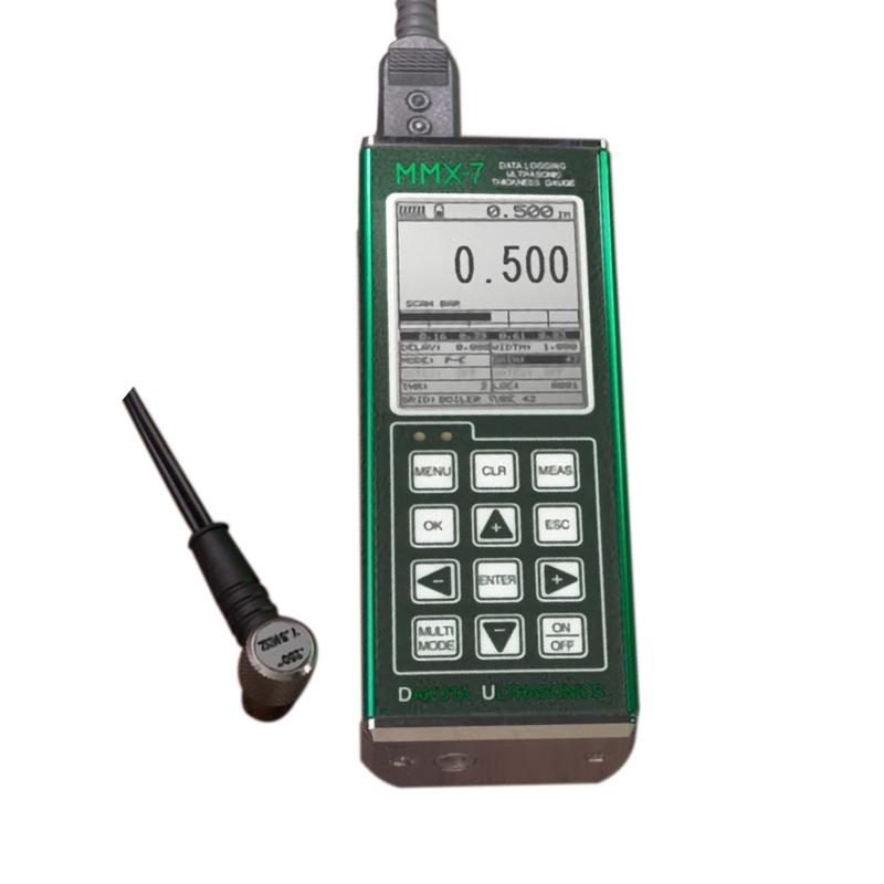
Introduction
The MMX-7 v2.0 has all the features of a ZX pressure gauge plus some other features and benefits. Selectable large digital and B-scan display options, internal 4Gb SD memory, alphanumeric data storage format, 64 user-defined settings, transducer list for improved linearity, echo echo via paint at the touch of a button, multiple calibrations and optional material type options, and more. It's all nicely packed in a very small portable aluminum profile for durability and portability! Our Java-based DakView PC or MAC OSX software and USB-C connectivity make this a complete toolkit!
Product Applications
Corrosion & Pitting, Boilers, Tubes, Glass, Chariots and many other applications.
Instrument display structure diagram
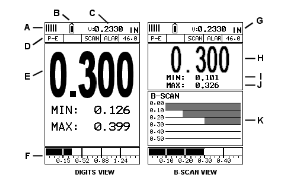
A. Repeatability/Stability Indicator – This indicator should generally be used in conjunction with the numeric thickness values displayed. When all vertical bars are fully lit and the last digit of the digital thickness value is stable, the MMX-7 reliably measures the same value 250 times per second (250 Hz).
B. Battery icon – indicates the remaining battery life of the MMX-7.
C. Speed – The velocity value of the material currently used or calibrated by the MMX-7. Displays in imperial or metric units, depending on the unit in which the gage is set.
D. Feature Status Bar – Indicates the features that are currently enabled and in use in the following order:Measurement Mode,Difference mode,High-speed scanning mode,Alarm mode,Gain setting.
E. Numeric Material Thickness Values – Extra-large font size for easy viewing.
F. Scan Bar – Another view of the material thickness in the horizontal bar of the deflection style. This is a vision tool that enables users to see thickness changes from defects and pits during high-speed scanning.
G. Units – The units of measurement (imperial, metric) currently in use.
H. Numeric Material Thickness Values – Smaller font size when B-scan display view is enabled.
I. Minimum material thickness – part of the scanning function. Displays the minimum thickness value found during the scan.
J. Maximum material thickness – part of the scanning function. Displays the maximum thickness value found during the scan.
K. B-scan display – cross-sectional view of the material. Provide the user with a graphical view of the relative/blind surface (i.e., the inner surface of the pipe wall) to give the user an idea of the condition or integrity of the material being measured.
- 1Principle of Portable Ultrasonic Thickness Gauge
- 2Measurement principle and influencing factors of high temperature ultrasonic Thickness Gauge
- 3Types and Usage Methods of Coupling Agent for Thickness Gauges
- 4The Principle, Application and Precautions of Copper Plate Ultrasonic Thickness Gauge
- 5Principle, Application and Selection of Ceramic Ultrasonic Thickness Gauge
- 6Principle, Application and Type Selection of Ultrasonic Thickness Gauge
- 7Principle, Application and Type Selection of Ultrasonic Thickness Gauge
- 8Thickness of dry film - cement substrates, gypsum and drywall (ASTM D6132 and SSPC-PA 9)
- 9How to choose a portable Thickness Gauge?
- 10How to Use Ultrasonic Thickness Gauge Correctly
马景铎,马天燕 - 《河北省计量监督检测院 廊坊分院》