
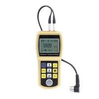
DAKOTA CMXDL Ultrasonic Coating Thickness Gauge
 CMXDL
CMXDL

DAKOTA CMXDL Ultrasonic Thickness GaugeSPEC
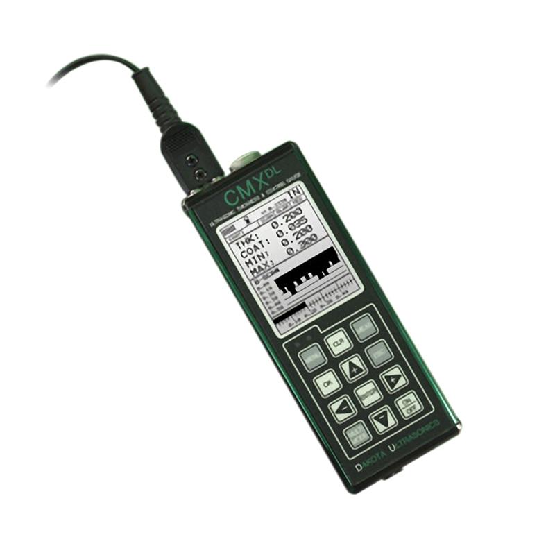
DAKOTA CMXDL Ultrasonic Thickness GaugeDetails
DAKOTA CMXDL Ultrasonic Thickness GaugePacking list
- SKU
- NB029553
- Measurement range
- 1.0~152mm
- Probe Frequency
- 5MHz dual crystal probe
- Probe style
- Split probe
- Probe diameter
- Φ6.35mm
- Probe line length
- 4 foot cable
- Display resolution
- +/- .001 inches (0.01 mm)
- unit system
- Imperial and metric systems
- Calibration method
- Single-point and two-point calibrating options for materials and coatings, or select the basic material type
- Measurement mode
- Coatings Off: Pulse Echo PE, coatings: Pulse Echo coating PECT, temperature compensation: Pulse Echo PETP, Pass-through drawing: Echo-Echo (EE), Penetration verification: Echo-Echo verification E-EV, coatings only: coatings CT
- Measurement speed
- 0.0122 to 7300 in./ms (309.88 to 18542 m/s)
- Storage Capacity
- 4 Gb Internal SD Card
- Display
- 1/8 in. VGA gray scale display (240x160 pixels). Viewing area 62x45.7 mm (2.4 x 1.8 in). EL backlight (On/Off/Auto)
- Operating language
- English
- Interface
- Direct USB-C 1.1 PC connection
- Environmental temperature
- -14 ° to 140 ° F (-10 ° to 60 ℃)
- Power Supply
- Three 1.5V alkaline or 1.2V NiCad AA batteries
- Operating Time
- NI-MH and alkaline batteries: gray scale 35 hours, color 12 hours. Nicad: gray scale 10 hours, color 5 hours.
- Host size
- 63.5*165*31.5mm
- Weight
- 13.5 ounces (with battery)
- keyboard
- A membrane switch with 12 tactile keys
- Certificate type
- Factory calibrated to NIST and MIL-STD-45662A
- probe interface
- Lock the "00" LEMO Connector that disconnects quickly
- pulse generator
- Double square wave pulse generator
- receiver
- Dual Receiver Manual or AGC gain control with 110dB range (limited)
- Timer
- Precise TCXO Timing with Single Pulse 100MHz 8-Bit Ultra-Low Power Digitizer
- Pulse echo mode (PE)
- (Pit and defect detection) Measurement range 0.63 to 1219.2 mm
- Pulse echo coating mode (PECT)
- (Material, coating, pit and defect detection): Material: 0.63 to 1219.2 mm. coating: 0.01 to 2.54 mm
- Pulse echo temperature compensation mode (PETP)
- (Pit and defect detection) Automatic temperature compensation - Measurement range 0.63 to 1219.2 mm
- Echo Mode (EE)
- Dimensions through coatings and coatings are 2.54 to 152.4 mm
- Echo Mode (E-EV)
- Dimensions of 1.27 to 25.4 mm through coatings and coatings
- Only coating mode (CT)
- (Coating thickness) 0.0127 to 2.54 mm
- screen capture
- Bitmap graphics capture for quick documentation (.tif)
- log format
- Grid (alphanumeric) sequence (automatic identifier)
- Automatic shutdown
- After 5 minutes of free time
Introduction
The CMX DL v2.0 has all the features of CMX and has a large storage capacity of 4 Gb using multiple file structures, as well as graphic capture for fast documentation of (.tif) file formats. Choose between the following file formats: sequential (with automatic identifiers) or standard alphanumeric grid format for data reporting.
The suite includes our DakView java-based PC or MAC OSX software for transferring, viewing, and creating custom reports. Export to .csv format for import into a text editor or spreadsheet-based package. USB-C connection.
Features
Measurement modes: Pulse-Echo, Pulse-Echo with Coating, Pulse-Echo with Temperature Compensation, Echo, Echo Verification and Coating-Only.
Automatic: Probe zeroing, probe identification and temperature compensation.
Store up to 64 custom settings for specific applications.
High-speed scanning with up to 250 readings per second.
Audible and visual alarms have upper and lower limit settings.
Built-in differential mode for QC inspection.
Time-based B-scan functionality is available for cross-sectional material scanning.
Data storage format: Alpha numeric grid and sequential w/auto identifier.
Comes with Windows PC or MAC OSX software.
Diagram of the display structure
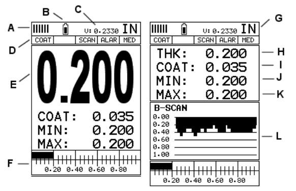
A. Repeatability/Stability Indicator – This indicator should generally be used in conjunction with the numeric thickness values displayed. When all vertical bars are fully lit and the last digit of the digital thickness value is stable, the CMXDL reliably measures the same value approximately 250 times per second, depending on the measurement mode and function enabled.
B. Battery icon – indicates the remaining battery life of the CMXDL.
C. Velocity – The velocity value of the material currently in use or calibrated by CMXDL. Displayed in imperial or metric units, depending on the unit of the gauge.
D. Feature Status Bar – Indicates the features that are currently enabled and in use in the following order:Measurement Mode,Difference mode,High-speed scanning mode,Alarm mode,Gain setting.
E. Numeric Material Thickness Values – Extra-large font size for easy viewing.
F. Scan Bar – Another view of the material thickness in the horizontal bar of the deflection style. This is a vision tool that enables users to see thickness changes from defects and pits during high-speed scanning.
G. Units – The units of measurement (imperial, metric) currently in use.
H. Numeric Material Thickness Values – Smaller font size when B-scan display view is enabled.
I. Coating Thickness Value – Shows the actual thickness of any coating adhering to the surface of a metallic material (PECT mode) or the actual thickness of the coating adhering to a non-metallic surface (CT mode).
J. Minimum material thickness – part of the scanning function. Displays the minimum thickness value found during the scan.
K. Maximum material thickness – part of the scanning function. Displays the maximum thickness value found during the scan.
L. B-scan display – a cross-sectional view of the material. Provide the user with a graphical view of the relative/blind surface (i.e., the inner surface of the pipe wall) to give the user an idea of the condition or integrity of the material being measured.
- 1Use of Ultrasonic Thickness Gauge and its indication
马景铎; 马天燕 - 《如何正确使用超声波测厚仪》
- 2Principle of Portable Ultrasonic Thickness Gauge
- 3Measurement principle and influencing factors of high temperature ultrasonic Thickness Gauge
- 4Types and Usage Methods of Coupling Agent for Thickness Gauges
- 5The Principle, Application and Precautions of Copper Plate Ultrasonic Thickness Gauge
- 6Principle, Application and Selection of Ceramic Ultrasonic Thickness Gauge
- 7Principle, Application and Type Selection of Electronic Coating Thickness Gauge
- 8Principle, Application and Type Selection of Ultrasonic Thickness Gauge
- 9Principle, Application and Type Selection of Ultrasonic Thickness Gauge
- 10Four Methods of Ultrasonic Thickness Gauge measurement