

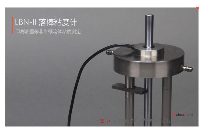
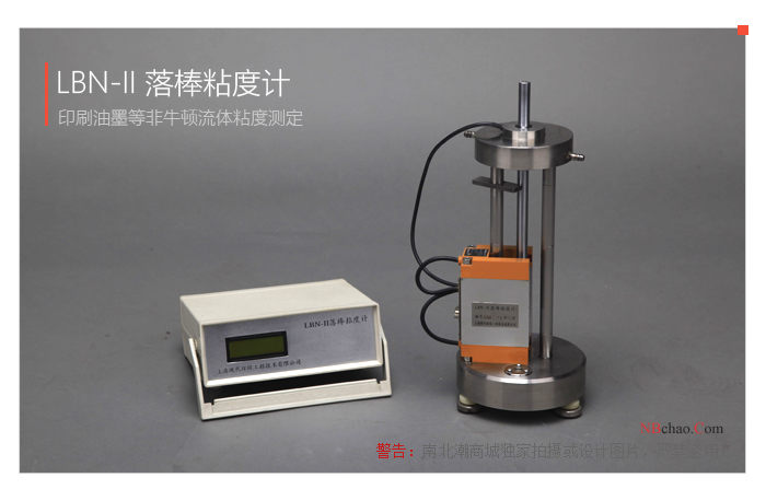
MODERNER LBN-II Falling Rod Viscometer Printing ink Determination of non-newtonian fluid viscosity
SE LBN-II

Moderner LBN-II Falling Rod ViscoMeterSPEC
Moderner LBN-II Falling Rod ViscoMeterDetails
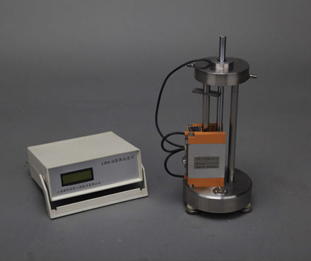
Moderner LBN-II Falling Rod ViscoMeterPacking list
- SKU
- NB000719
- Display
- digital display
- Viscosity range
- 2000~200000mPa·s
- Power
- 220v 50Hz
- Application standard
- ISO12644:1996 (E) "Printing Technology - Determination of Rheological Properties of Slurry inks and Their Linkers by Falling Rod Viscometer"
- Operating Environment
- The temperature should be kept at 25 ℃ +/- 2 ℃
- Overall Dimensions
- 140*140*300mm
- Instrument Weight
- 18kg
- Drop rod size
- Φ12x300mm
- Drop Weight
- 132g
- Weight group grams
- 25-50-100-200-200-500-1000-1000-1000g(共4075g)
- Drop rod drop time Accuracy
- 0.01s

Introduction to the LBN-II drop rod viscometer
The LBN-II drop rod viscometer is an effective experimental equipment that consists of a controller and a drop rod device, and determines the apparent viscosity of the ink by applying printing ink to the drop rod to test the falling time. rootThe LBN-II drop rod viscometer is produced in a MODERNER and measures viscosity in the range2~200Pa·s, the temperature and time are displayed through the display screen of the controller, and the good parts make the whole drop rod viscometer not only stable and reliable but also accurate in measurement.
An overview of the principles of a drop rod viscometer
The LBN-II drop rod viscometer (also known as Larley viscometer) is a commonly used instrument for determining certain rheological properties (apparent viscosity, false yield value, shortness, etc.) of non-Newtonian fluids (fluids whose viscosity varies with shear rate) such as printing inks. It is generally believed that the results of the Lray's drop rod test can describe part of the rheological properties of the ink in the printing process satisfactorily, which is suitable for the actual control of viscosity during the production of ink, and is often used as a technical requirement for acceptance by both buyers and sellers. LBN-II Drop Rods Viscometer is based on the international standard ISO12644: 1996 (E) "Printing Technology - Determination of Rheological Properties of Slurry Inks and Their Connecting Materials Using Drop Rods Viscometer" Designed and manufactured, it is designed and manufactured by measuring the time required for different loads to fall through the pores of the test sample, with the help of an appropriate flow model (Carson model, Bingham model or exponential law model), by applying a linear regression method to obtain the apparent viscosity of the sample (the viscosity value at a certain shear rate, the apparent viscosity obtained by the Pulley drop rod test is sometimes called the puller viscosity), yield value and shortness ratio (often referred to as shortness).
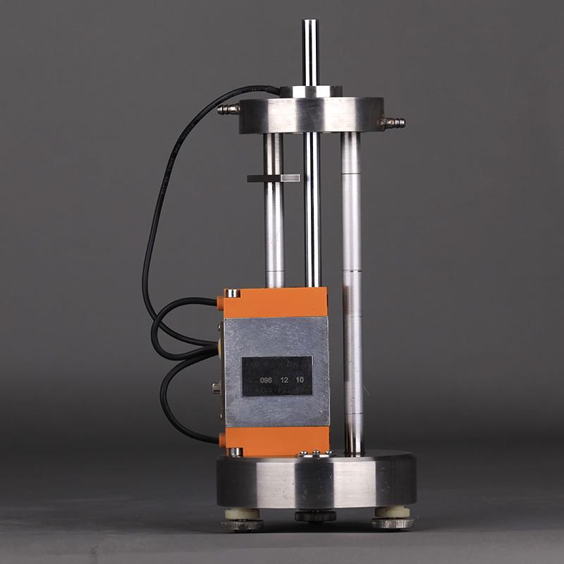
Product diagram of the drop rod viscometer

Outline and structure diagram of the falling rod viscometer
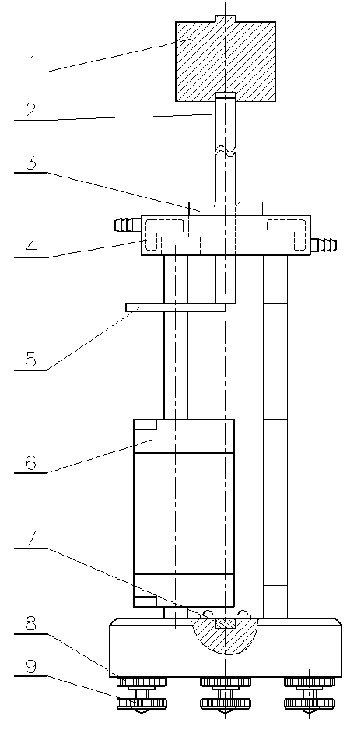
1. Load weight 2, drop bar 3, guide bushing 4, constant temperature water jacket 5, rotating baffle 6, photoelectric switch 7, level 8, fixing nut 9, adjusting screw
Test experiment of a drop rod viscometer
(1) Operational preparations
1) Take out the MODERNER LBN-II drop rod viscometer from the box and place it on the workbench and adjustLBN-II drop rod viscometerLevel.
2) Plug in the signal connection cable plug and insert the temperature sensor into the inclined hole of the drop rod guide sleeve.
3) Connect the two latex pipes leading out of the thermostatic sink (need to be purchased separately) with the thermostatic water jacket respectively.
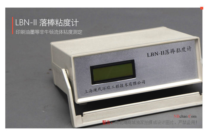
4) Turn on the power and turn on the thermostatic sink andLBN-II drop rod viscometerThe power switch of the control box, the display shows that the temperature is the Celsius temperature of the current guide bushing, and the time is displayed as 0.00 seconds. (Note: The specific operation method of the thermostatic sink is shown in the manual of the thermostatic sink.) )
5) The laboratory temperature should be maintained at 25 °C±2 °C throughout the assay period. When the guide sleeve temperature reaches 25°C ± 0.2°C specified in the standard, the measurement can be started.
6) In order to reduce the temperature rise caused by the human body temperature as much as possible during operation, it should be avoided to contact the drop rod and guide sleeve of the viscometer with bare hands. Wear gloves or put a small piece of cotton cloth in your hand when you need to touch the drop rod or guide sleeve.
(2) Summary of operations
1) Before the measurement, take about 5g of the tested sample each time, mix it on the glass plate with a small ink knife, and check that there are no coarse particles and impurities. The amount of sample to be measured should be sufficient to cover the annular groove of the drop rod guide bushing.
2) Insert the drop rod vertically into the guide bush hole of the drop rod and gently lower it to the rotating baffle. Use a plastic ink knife to spread the evenly mixed sample in the groove of the drop rod and the annular hole of the guide bush, gently rotate the drop bar to evenly distribute the test sample around the groove, and gently lift the drop rod about 20 mm from the bottom of the drop bar with your fingertips to keep the test sample as close to the bottom of the tank as possible, release your finger to let the drop rod fall to the rotating baffle to ensure that the groove is full of the test sample.
3) Select any load weight to be placed on the top of the drop bar, remove the rotating baffle to make the drop bar fall, let the measured sample wet the drop bar and guide bushing, and at the same time, please confirm that the photoelectric switch and temperature sensor are working normally (the temperature is fixed at the beginning of the fall, and the time is displayed as the fall meter seconds; the temperature at the end of the fall is displayed as the temperature at the end of the fall, and the time is displayed as the actual falling seconds; the temperature recovery after pulling the drop bar is displayed as the measured temperature of the guide bushing, and the time is automatically cleared).
4) Avoid any operation that may scratch the falling rod, and it is not allowed to use a metal squeegee to operate the falling rod, and it is not allowed to do the falling operation without the measured sample. Once the drop is complete, gently pull up the drop bar and rest it on the rotating baffle. Use a plastic ink knife to scrape the ink off the drop rod and apply it to the lower part of the drop stick and in the annular groove of the guide bush.
5) Select the appropriate load weight combination: select the weight according to the above 3~4 steps for the fall test, in order to confirm that the falling time of the selected maximum load weight is in the range of 4~10 seconds (the American standard ASTM D4040-05 recommends that it be as close as possible to 1~2 seconds), and the falling time of the rest of the weights does not exceed 60 seconds. Usually 4~5 load weight combinations of different weights are selected.
The ISO standard recommends the following combinations of load weights: (unit: g)
| A: | 5000 | 4000 | 3000 | 2000 | 1000 |
| B: | 3000 | 2000 | 1500 | 500 | |
| C: | 1500 | 1000 | 800 | 500 | |
| D: | 800 | 600 | 400 | 200 | |
| E: | 400 | 300 | 200 | 100 | |
| F: | 200 | 100 | 50 | 0 |
6) The measurement of the measured sample starts from the heaviest weight in the weight combination, and the heaviest weight must be at least two falling times of no more than 0.5 seconds, and the lighter weight can be replaced in turn for measurement. Before starting the measurement, prepare the tested sample according to the above 1~2 steps; every time the drop is completed, the ink on the drop rod needs to be scraped off with a plastic ink mixing knife, and it is applied to the lower part of the drop rod; the measured sample shall not be added to the measurement; if the measured sample is found to be insufficient during the measurement, clean the drop rod and the guide bush, and then take a new test sample and repeat the above 1~2 steps. The weights of each weight were measured 3 times, and each time the falling time of the rod (accurate to 0.01 seconds) and the temperature of the guide sleeve (accurate to 0.1°C) were recorded.
7) The measurement operation should be swift and uninterrupted, and the entire operation should be completed within 5 to 10 minutes. Many printing inks and binders contain highly volatile solvents, and unless the actual exposure time is strictly controlled, the volatilization loss during operation can cause large deviations in the measurement results. If it is found that the falling rod of the same load weight will be longer several times in a row, it means that there is a significant volatile loss (it is advisable to choose a heavier weight combination to reduce the measurement time).
8) Viscosity determination has a strong sensitivity to temperature, so the temperature needs to be controlled and monitored during the measurement process. In principle, if the temperature of the guide sleeve exceeds 25.2°C before operation, the temperature control equipment needs to be reset, and if the temperature of the guide sleeve changes more than 25°C ±1°C during the whole measurement, the test needs to be redone.
9) Do it in time after the measurement is completedLBN-II drop rod viscometerThe cleaning and maintenance work, especially the cleaning of the rod drop and the guide sleeve, must be timely, careful and effective. Cleaning should be done using a lint-free cloth or paper and an appropriate solvent.
(3) Summary of data processing
1. Refer to the ISO standard to define the instrument constants α and β as follows:
 --------------------------------(1)
 ---------------------------(2)
Where: L —— the distance of the falling rod (m)
s —— Sample film thickness between the gap between the drop rod and the guide sleeve (m)
g —— Acceleration due to gravity (9.80665m/s2)
π—— Pi (take 3.14159)
r —— rod drop radius (m)
l —— Length of the equivalent cylindrical part of the guide bushing (m)
2. The shear rate and shear stress can be obtained as follows:
 ---------------------------------(3)
 ---------------------------- (4)
Where: γ—— Shear rate (s-1)
t —— Falling time of the rod (s)
σ —— Shear stress (Pa)
m —— Total mass of drop bar and load weight (kg)
3. The viscosity can be obtained by the following formula
-------------------------------- (5)
Where: η - viscosity (Pa·s)
4. For Newtonian fluids, viscosity is an immutable constant, and the viscosity value of the measured sample can be obtained by simply taking the average value calculated by each measurement result. However, the drop rod viscometer is mainly used to determine the viscosity of non-Newtonian fluids, and the viscosity varies with the shear rate, and the viscosity value obtained after the calculation of each measurement result is different. To distinguish viscosity values from Newtonian fluids, these different viscosity values for non-Newtonian fluids are often referred to as apparent viscosity. In order for the apparent viscosity values to be comparable, uniform shear rate values need to be specified. The ISO standard specifies the apparent viscosity value at a shear rate of 2500s-1 (which is generally considered appropriate for describing the rheological properties of printing inks) as the apparent viscosity (sometimes referred to as Larley viscosity) of the sample being measured.
5. In order to derive the apparent viscosity at 2500s-1 shear rate from each group of measurement data, it is necessary to make certain assumptions about the functional relationship between shear stress and shear rate, which is usually called a flow model. The ISO standard recommends three flow models: Carson, Bingham, and exponential, and states that all three models are suitable for describing the rheological properties of certain printing inks and should be selected by the user according to the actual situation. It is also pointed out that there is no transformation formula between the three models.
6. Although the ISO standard recommends three flow models, the drop rod viscometer usually uses the exponential law model for data processing (in ASTM D4040-05 "Standard Test Method for Rheological Properties of Slurry Inks and Their Connecting Materials Using a Drop Rod Viscometer", only the treatment method of the exponential law model is recommended). Therefore, the measurement data processing part of this manual only deals with this method (please refer to the ISO standard for the processing of the rest of the flow models). In fact, the ASTM standard describes the operating process in much more detail than the ISO standard, and can also be used as a reference (but the ASTM standard is rightLBN-II drop rod viscometerThe specifications and calculations of the parameters are different from the ISO standard, so please be careful when reading).
7. The exponential law model defined by the ISO standard is as follows:
 -------------------------------(6)
where: k – a constant related to the viscosity of the fluid
N – a constant that characterizes the degree of non-Newtonian properties of a fluid
8. For Newtonian fluids, N=1;N<1 non-Newtonian fluids are shear-thinned fluids (pseudoplastic fluids), and most printing inks are shear-thinned; N>1 non-Newtonian fluids are shear-thickened fluids (bulging fluids), which usually do not exist for printing inks and their connecting materials. If the measurement result is greater than 1~1.05, check the measurement data or redo the measurement.
(4) Measurement data processing
1. If the temperature exceeds the range of 25 °C ± 0.2 °C during the measurement, the falling time should be corrected as follows:
t=t[1+δt(T-25)]
Where: t - corrected fall time (s)
t-measurement – the recorded fall time (s, averaged for the same weight) at the time of measurement
δt - temperature correction factor, for printing inks, 0.1 is recommended
T measurement – the temperature recorded at the time of measurement (°C, averaged for the same weight drop)
2. The falling mass m is the total mass (kg) of the falling rod and the load weight. Substituting the t,m values of each group into equations (3) and (4) to obtain the σ and β values for each group (instrument constants and accompanying instruments have been given).
3. Take the logarithm of the two sides of the exponential law model equation to obtain the following linear relation:
logσ=logk+Nlogγ
Using the σ obtained in step 2, log k and N can be obtained by linear regression of the γ values to the above equation, and then k and N can be obtained.
4. The correlation coefficient of linear regression is used as the basis for judging the validity of the measured data: if the correlation coefficient is greater than or equal to 0.999, the result is considered valid, and if the correlation coefficient is low, the measurement needs to be redone.
5. The measurement results are calculated according to the following formula:
Apparent viscosity (larey viscosity = k·2500N-1)
False yield stress (yield value) = k·2.5N
Shortness ratio (or shortness) = false yield stress/apparent viscosity
6、LBN-II drop rod viscometerCalibration is required before leaving the factory and after a certain period of use. IfLBN-II drop rod viscometerIf the measured viscosity differs by more than 20% from the standard oil viscosity data, the combination of the drop rod and guide bush needs to be replaced, and if the difference does not exceed 20%, the viscosity correction factor can be used to compensate. The apparent viscosity is calculated as follows:
Apparent viscosity = δ·k·2500N-1
7. The above is a brief description of the measurement data processing, and the actual calculation is done by computer software (the software is provided by the included CD-ROM).
Precautions for use
1. The drop rod, guide sleeve, photoelectric switch and control box need to be paired and used according to the number, and cannot be cross-mixed between instrumentsLBN-II drop rod viscometerThe instrument constants given, invalid.
2. The drop rod and guide bush belong to precision parts, and their accuracy directly affects the measurement data. Therefore, the sample must not contain high-hardness impurities, and the ink knife used to scrape the ink also needs to use plastic or other soft materials to avoid scratching the drop bar.
3、LBN-II drop rod viscometerThe constants and viscosity correction coefficients are measured by the company's inspectors before leaving the factory and are given on a CD-ROM that comes with it.
4. In the process of use, the drop rod and the drop rod guide sleeve will inevitably be worn.LBN-II drop rod viscometerThe constants and viscosity correction coefficients also vary accordingly, thereforeLBN-II drop rod viscometerIdentification and correction should usually be done once a year.
5. The drop rod viscometer is used in the testing process of chemical raw materials, and the user should establish appropriate safety and protective measures and determine the rules and regulations in accordance with the relevant safety regulations before use. Safety issues related to contact with chemical raw materials shall be established by the user and shall not be within the scope of this manual.
- 1ISO 《Glass - Viscosity and Viscometric Fixed Points - Part 5: Determination of Working Point by Sinking Bar Viscometer First Edition》
- 2GB/T 13217.4-2020《Test method for viscosity of ink》
- 3GB/T 13217.5-2008《Test method for initial dryness of liquid ink》
- 4GB/T 22770-2008《Graphic technology - Determination of rheological properties of paste inks and vehicles by the falling rod viscometer》
- 5GB/T 22235-2008《Determination of liquid viscosity》